Loxone Maxx Control plugin
Categories:
Loxone integrators can control one Innosonix amplifier via Maxx Control using the Loxone Library plugins and example templates. Install the add-ons into Loxone Config, point each instance at the amp IP (or hostname.local), and drive mute, volume, and status over the device REST API.
What is the Loxone Maxx Control plugin?
The Loxone Maxx Control integration is a set of .LxAddon plugins from the Loxone Library that talk to a single amplifier’s Maxx Control REST API. Instantiate a plugin once per physical device.
Which Loxone templates do I need?
Because Loxone can only combine either Virtual Inputs or Virtual Outputs in a template file, two different templates have to be installed:
- MAXX-CONTROL which allows to set parameters to the amplifier
- MAXX-STATUS fetches Data from the Amplifier, mainly intended for Channel and Device Status
It’s totally valid to use only one, depending on your needs.
Installation
Download the corresponding .LxAddon Files and install it into your Loxone Config by double clicking or via the Import wizard like:

General
Both Plugins can be instantiated multiple times, as often as you want to control physical devices.
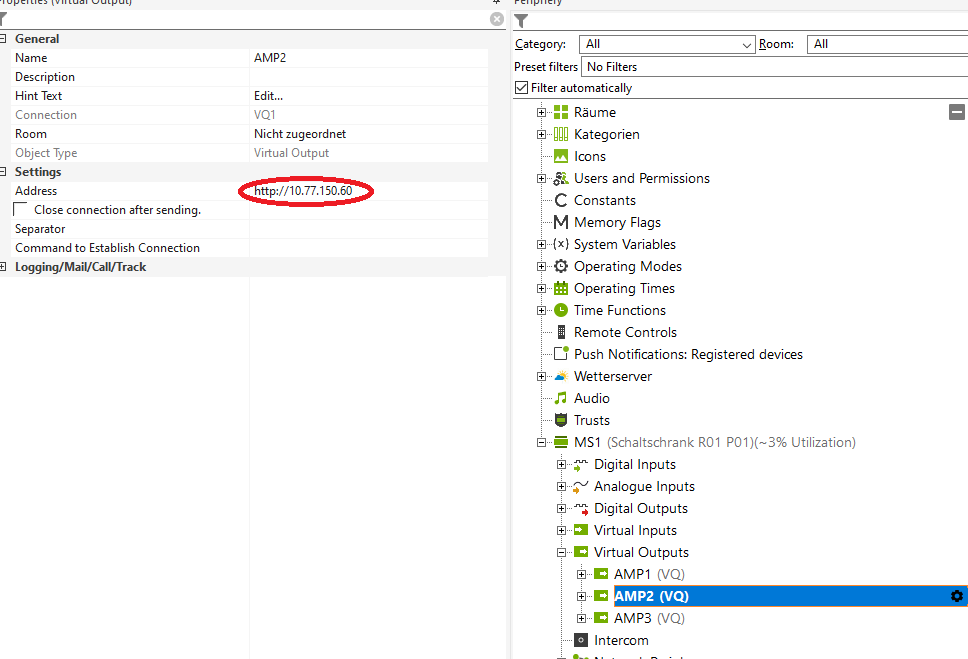
Please change the IP address for each device to its static IP or hostname.local. Leading http:// must be prepended, e.g. http://amp1.local or http://10.77.178.20.
For MAXX-STATUS a trailing /rest-api/status is required as well, like http://10.77.150.60/rest-api/status
MAXX-CONTROL
Download the MAXX-CONTROL.Loxone example file from the Loxone Library
The Template basically provides the following predefined controls:
- Channel Power
- Channel Mute
- Channel Volume
- Device Identify
- Device Master Mute
- Device Master Volume
and some examples of how to create custom commands for improved performance.
Power / Mute
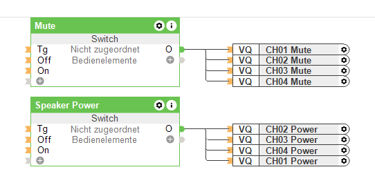
Simple digital outputs which can be grouped together in any desired combination.
Since each state change will send out a single HTTP request, this might cause a slight delay when a lot of channels are changed simultaneously. So, this kind of control is only recommended for a few channels. See Combined Commands to improve performance
Volume

Similar to Power / Mute Volume will send out any changes for each output as a single http request.
The interesting part here is how to map the common Loxone Analog Values in a range of 0-10 to a dB value for the amplifiers. That can be easily done with the Correction field of each output. The default configuration will map the values of 0-10 to -72dB - +10dB
This will give you almost the full dynamic range of the volume value:

It’s probably more useful to restrict the volume range accessible by the user to the desired listening levels like 0-10** to -20dB - -10dB or any other suitable range for your application
Combined Commands
A basic understanding of the REST-API interface is recommended to create those combined commands.
As a starting point, have a look at the three included examples:
- Multichannel Mute
- Multichannel Power
- Multichannel Volume
Those commands send the same value to multiple channels within a single HTTP request, significantly improving performance when many channels are involved in a call.
Multichannel Mute
Let’s have a look at the HTTP body which is sent out when the DIGITAL OUTPUT is set to ON by clicking on the edit button of that line:
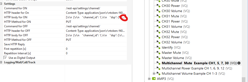
You basically see a JSON payload file containing an ARRAY of single JSON objects for the corresponding channels, indicated by the channel_id tag:
[
  {
    "channel_id": 1,
    "dsp": {
      "mute": {
        "value": true
      }
    }
  },
  {
    "channel_id": 5,
    "dsp": {
      "mute": {
        "value": true
      }
    }
  },
  {
    "channel_id": 7,
    "dsp": {
      "mute": {
        "value": true
      }
    }
  },
  {
    "channel_id": 30,
    "dsp": {
      "mute": {
        "value": true
      }
    }
  }
]
To modify that, simply duplicate the entries:
{
   "channel_id": 1,
   "dsp": {
      "mute": {
         "value": true
      }
   }
},
for each channel, you want to control and change the channel_id to the desired channel number.
Don’t forget the trailing comma "," after each object, except the last one! Please use any JSON validator to verify the final JSON object before putting it back into Loxone Config
Copy and paste the JSON payload to any text editor and replace the "value": true with "value": false and insert that object into the HTTP body for OFF
MAXX-STATUS
Download the MAXX-STATUS.Loxone example file from the Loxone Library
The MAXX-STATUS Template periodically polls the /rest-api/status URL of the amplifier and filters the response for each channel status/device status.

The raw CHxx STATUS value represents the default syslog severity levels like:
| STATUS | Level |
|---|---|
| 0 | EMERGENCY |
| 1 | ALERT |
| 2 | CRITICAL |
| 3 | ERROR |
| 4 | WARNING |
| 5 | NOTICE |
| 6 | INFORMATIONAL |
| 7 | DEBUG |
| 8 | OK |
In combination with the provided STATUS component with the following settings:
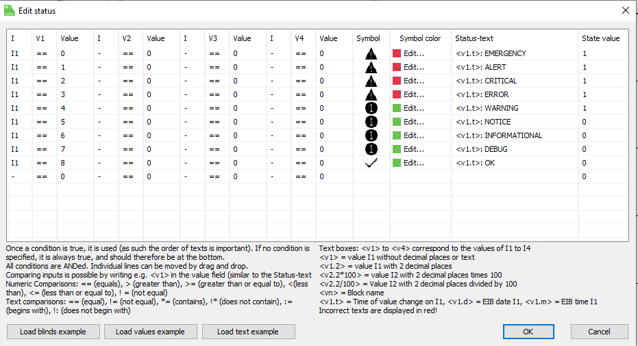
An easy virtualization can be achieved.
Combining the Val output of each STATUS component with an OR Gate, a simple GLOBAL STATUS can be generated when any channels or device assert any state higher than NOTICE ( see STATUS settings, State value).