Work in progress documentation.
This is the multi-page printable view of this section. Click here to print.
Maxx Remote
Maxx Remote Documentation
- 1: Concept
- 2: Installation
- 3: Quick-Start
- 4: Surround Input Sources
- 5: Multi-Way Channels
- 6: Speaker Presets
- 7: GUI
- 8: API
- 8.1: GROUP-SIGNAL-PATH
- 8.2: REST-API
- 8.3: VIEW API
1 - Concept
Basic concept behind MAXX Remote
… is, and abstraction layer between devices and just channels. It doesn’t matter if 1000 channel are spread out over 32x 32 Channel amplifiers, or 125x 8 Channel Amplifiers or any other combination.
As a user, you normally don’t want to know on which amplifier channel your speakers are mapped during operation and tuning of the system. The only thing that’s interests is that you want to control this specific channel or a group of channels in a room for example.
System Overview

Application / Server
MAXX Remote can be used in two different application forms:
- Desktop Application (multiplatform Windows / MAC / Linux)
- Server only as Docker Image Docker Hub
In both scenarios, the MAXX Remote system always consists of an SERVER and FRONTEND / USERINTERFACE / GUI part which is general a html webpage controlling the actual server.
The SERVER / Desktop application containing an integrated webserver where the USERINTERFACE is always accessible. Like on your local PC: http://localhost:8000
Objects
In MAXX Remote we distinguish between some basic object types:
-
CHANNELS or PROJECT CHANNELS
Represents a single amplifier channel which holds data for every possible DSP option. -
GROUP
Groups can control every parameters the channels offers but will affect multiple channel at once. -
DEVICES
Devices represents amplifier in your Project. Each Devices, depending on it’s type, offers a specific channel count like 8, 16, 24, 32. -
HW CHANNELS
are those hardware channel, present on devices in your project, like CH1 @ AMP1
How does this relates?
CHANNELS could be seen like regular channel strips on an amplifier device itself. That means, you can control this specific channel like you want.
If a CHANNEL is part of one or multiple GROUPS, those groups could also add some values to that channel. Depending on the parameter type, the overall summation of the channel value and all assigned groups will be the final output value of that channel.
| Source | Volume |
|---|---|
| Channel | -2dB |
| Group 1 | -1dB |
| Group 2 | +5dB |
| ________ | _______ |
| OUTPUT | +2dB |
If a CHANNEL is linked to a HW Channel (a channel on an Amplifier device), MAXX Remote will send the CHANNEL values to the device.

Since all channel settings are stored in the database of MAXX REMOTE, it’s easy to exchange a device or even reorder the channel assignment over devices.
OUT OF SYNC
Once a CHANNEL is linked to a device, MAXX REMOTE monitors those channel values on the device itself because it’s still possible to directly change channel values via MAXX CONTROL.
It’s not advisable to use MAXX CONTROL anymore if a device is controlled via MAXX REMOTE since the data direction is ALWAYS MAXX REMOTE to the device.
If any mismatch in data consistency is detected via the periodical check-in MAXX REMOTE, an OUT OF SYNC warning is asserted, which shows the affected parameters.
It’s the user’s responsibility to resolve those issues by either changing values in the MAXX REMOTE to align with the device or just overwriting the data in the device with those data stored in MAXX REMOTE.
2 - Installation
How to Install Maxx Remote?
Good part, it’s quite easy!
Desktop Application
Just download the application from our webpage
Those applications are portable, which means no installation is required, just start them.
Server / Docker
Simple Start
docker run --detach --name maxx-remote --network host innosonix/maxx-remote:latest
Note
The option --network host is not necessarily required, except if you want to use device discovery which is performed on UDP broadcast message on port 9453
If not used, must add Devices manually via their IP address.
Once the Docker Container is running, the integrated web server can be accessed via the IP address of the Docker on port 8000.
Manage the persistence
Warning
When starting the Docker Container without any attached volume, your whole project configuration is stored in the container volume itself.
AND WILL BE LOST once you delete the container or a new one is started
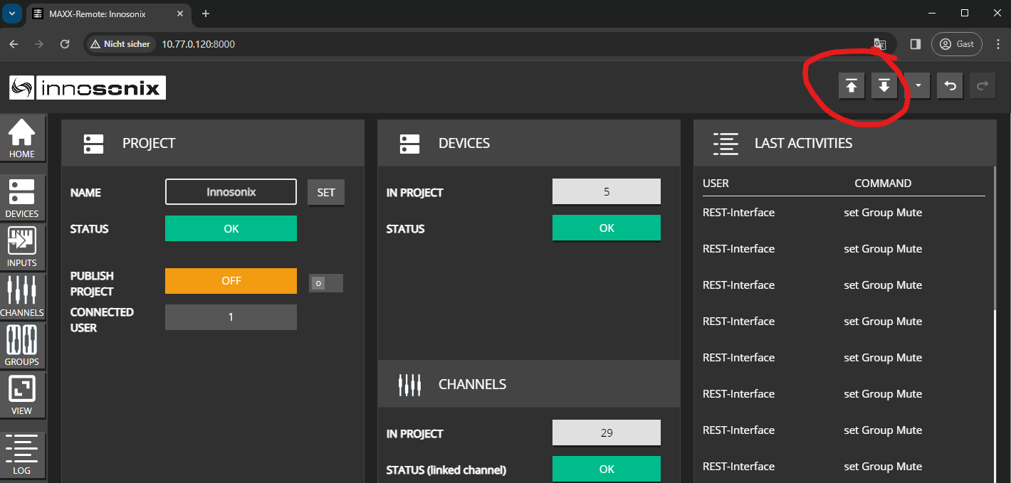
Manage it on your own
You can manage the project files by downloading/uploading the current runtime configuration when switching to a new container.
Using Docker Volumes
The preferable way is to use a dedicated docker volume to store the runtime configuration of the server.
# create a new volume ( only has to be done once )
docker volume create maxx-remote-volume

# start the container and mount the volume
docker run  --detach \
            --restart always \
            --name maxx-remote \
            --network host \
            --mount source=maxx-remote-volume,target=/root \
            innosonix/maxx-remote:latest
3 - Quick-Start
First music out of a device
Set up a simple demo scenario containing three speakers (Left / Right / Sub) connected to CH 1, 4, and 9 on an MA32/D², doing some equalization and routing music from a Dante Virtual Sound card.
Create Project
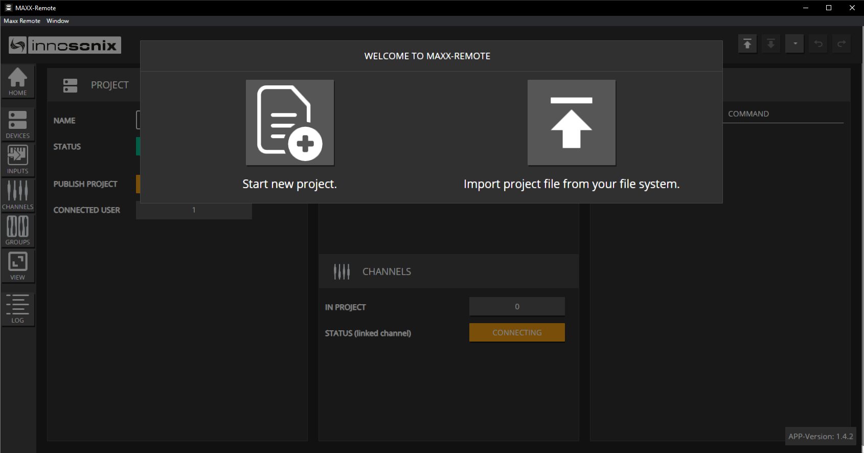
The first time you are going to Start the Maxx Remote, this splash screen appears. Click on Start a new project and type in any name.
Create Channels / Groups
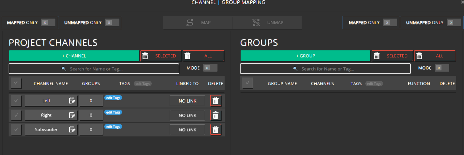
Let’s create our three required channels and one group containing all channels.
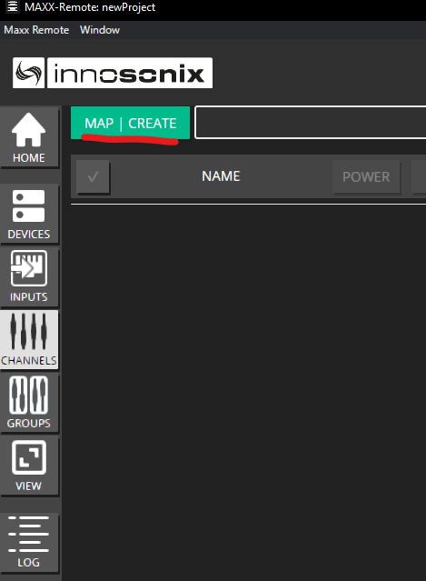
- Click on CHANNELS -> MAP | CREATE
- Click on + CHANNEL and enter 3 in that CHANNELS TO ADD field. We can now directly assign names to those channels.
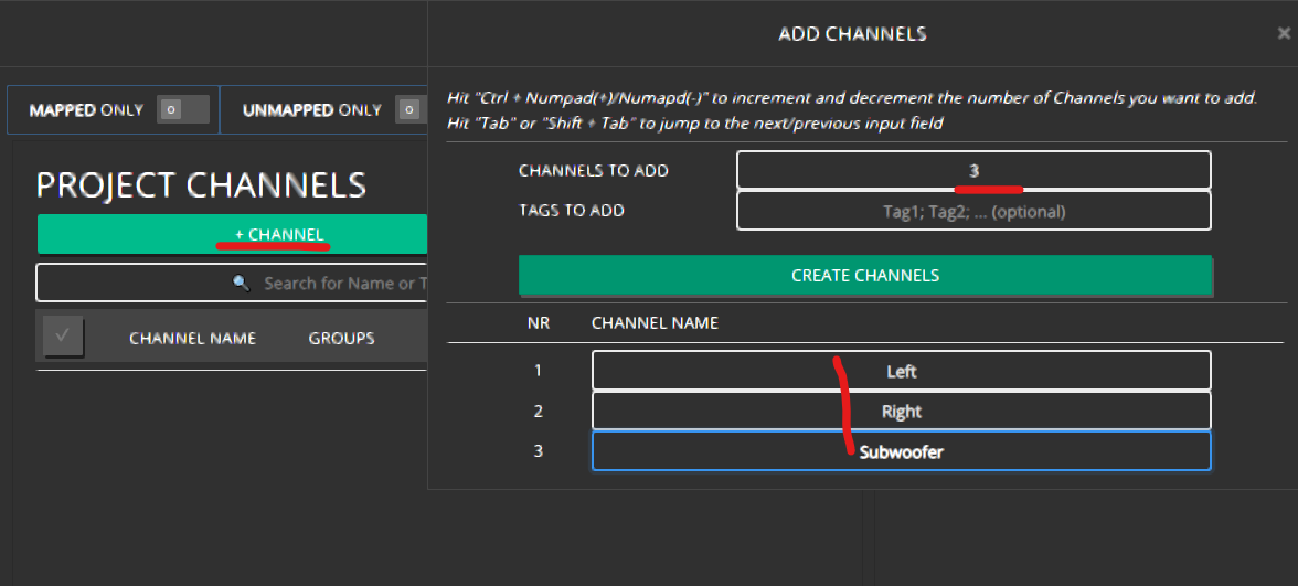 Finish that by clicking on CREATE CHANNELS
 - Our three PROJECT CHANNELS have now been created, as seen in the LINKED TO column; there is no link to an amplifier channel yet. Those channels can configure any settings without the need for actual hardware devices.
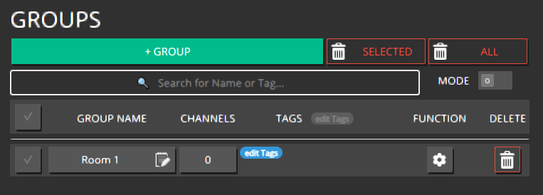
- Perform the same steps to create one Group by clicking on + GROUP and name it ROOM 1, for example
- Now assign the channels to that group by either Drag & Drop the selected channel to a group or selecting them and pressing the MAP button in the headline.
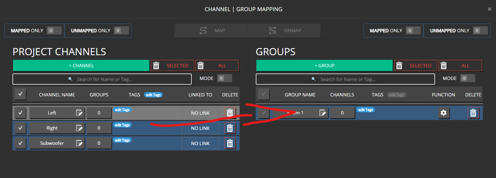 .
.Hint
A channel can be member of multiple groups simultaneously
Connecting to an amplifier
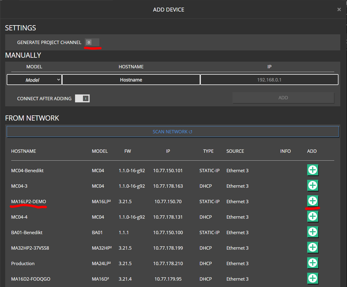
- Click on DEVICES -> ADD DEVICE. You can either add devices already found in your network or add them manually by specifying MODEL and HOSTNAME. Disable the GENERATE PROJECT CHANNELS since we don’t want to autogenerate all amplifier channels in our project.
Note
Adding an fixed IP is optional. If no IP is supplied, the hostname will be resolved via our discovery protocol. But for fixed installations, adding an IP is recommended to speed up the connection process.
- Once the Device is added, the Maxx Remote automatically tries to connect. The CONNECT switch can be used to disable any network activity.
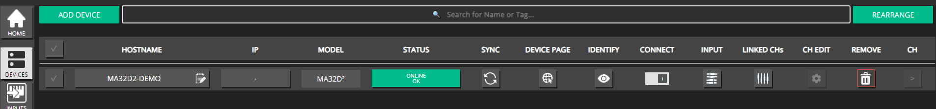
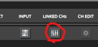
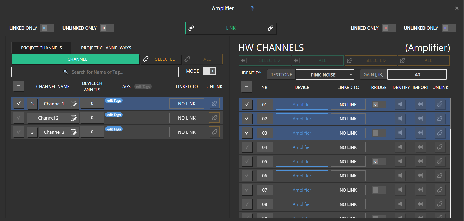
- We will link our PROJECT CHANNELS to the channels of the amplifier itself by clicking on the LINKED CHs icon.
- To ensure we link the correct channels, an IDENTIFY function is available to play a test tone (like PINK NOISE with a certain level -40 dB) on the corresponding channel.
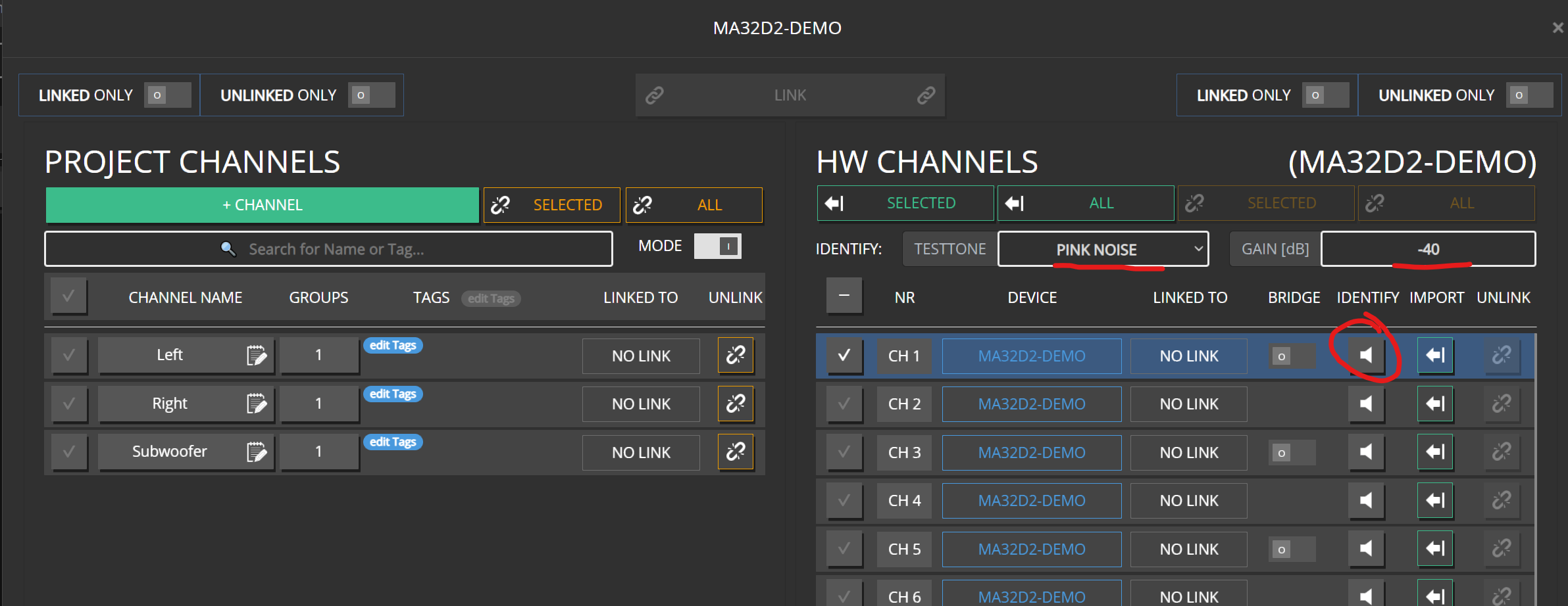
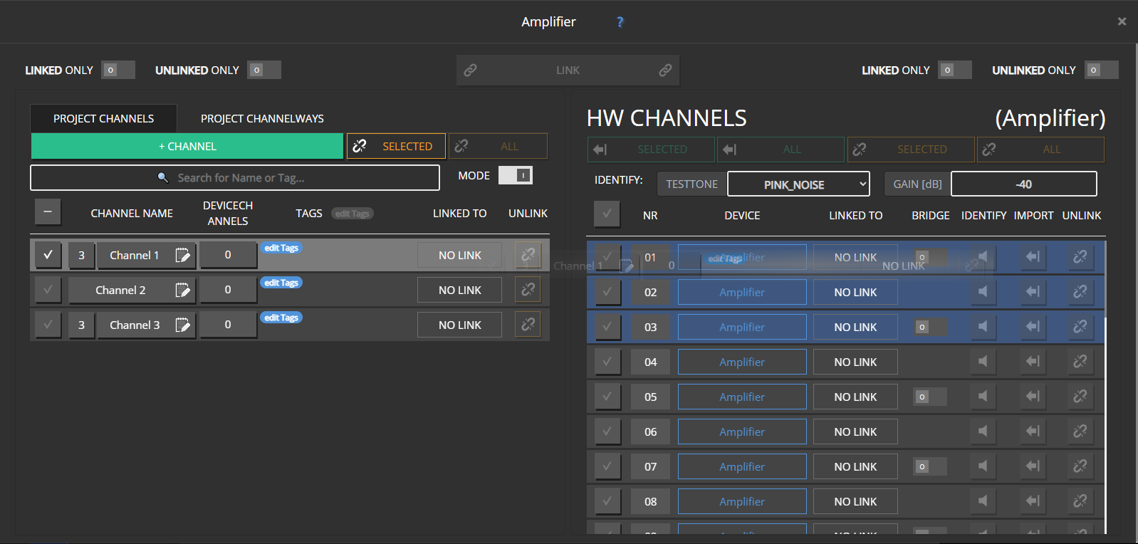
- Once the correct channel is found, link a PROJECT CHANNEL** to that HW CHANNEL by Drag & Drop or via the LINK button.
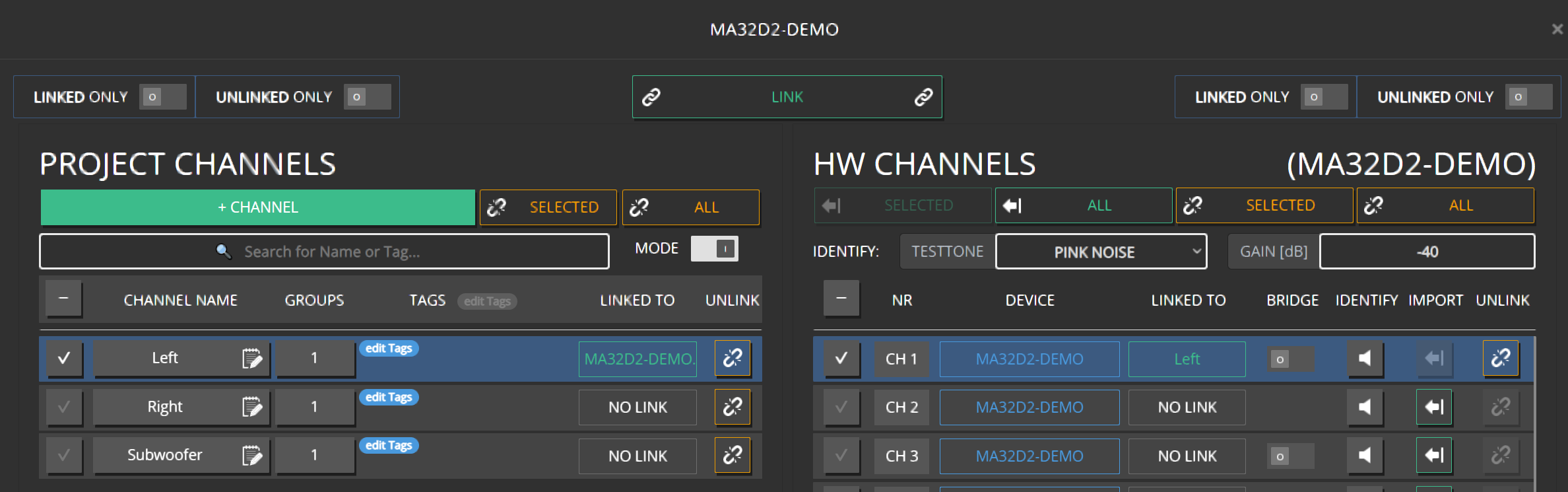
- Finish the linking of the remaining channels
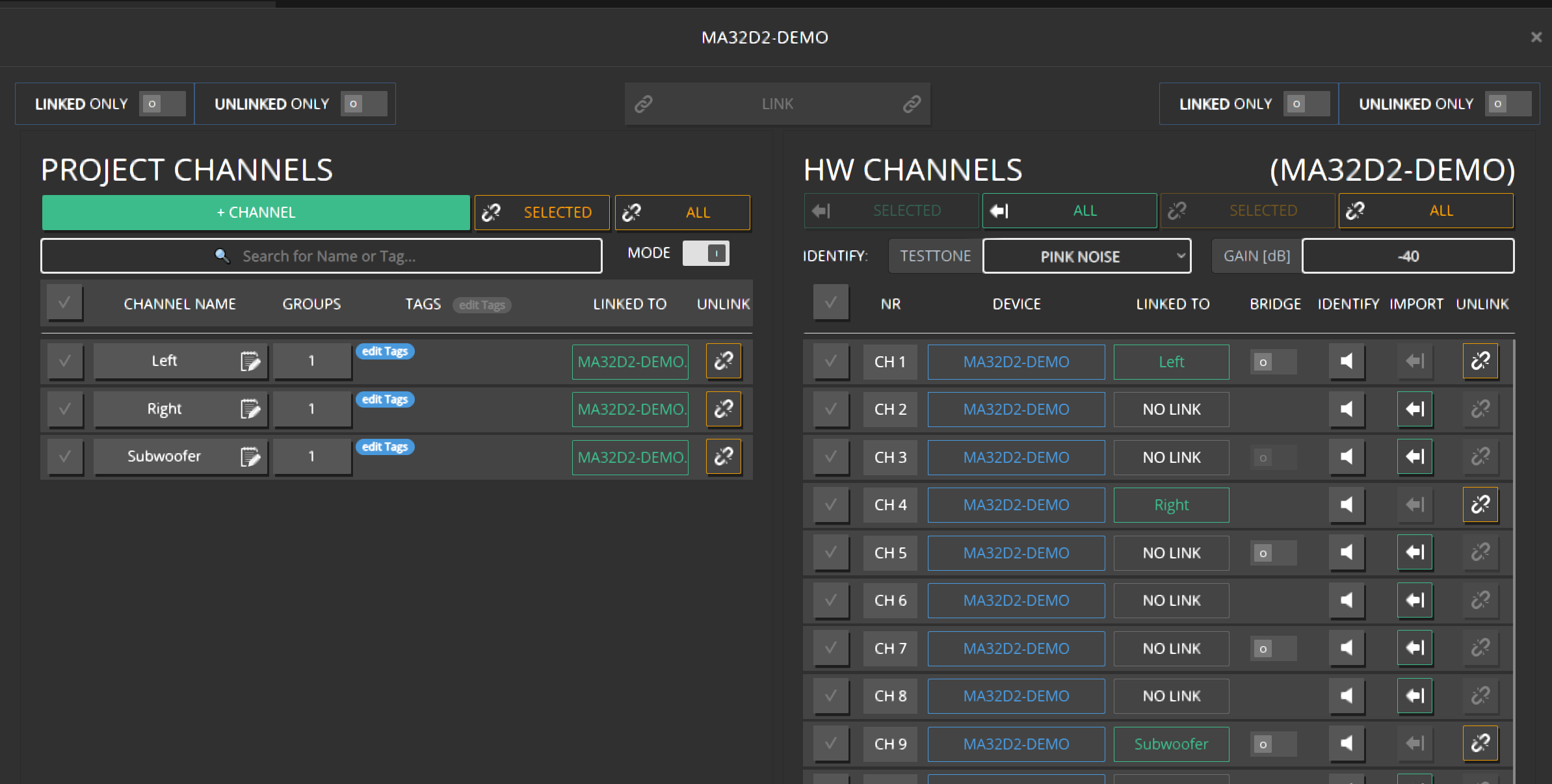
- The assignment can easily be reordered by Drag & Drop a HW CHANNEL to another empty slot or even swapping two channels by dragging one over an already assigned one.
Adjusting the Volume
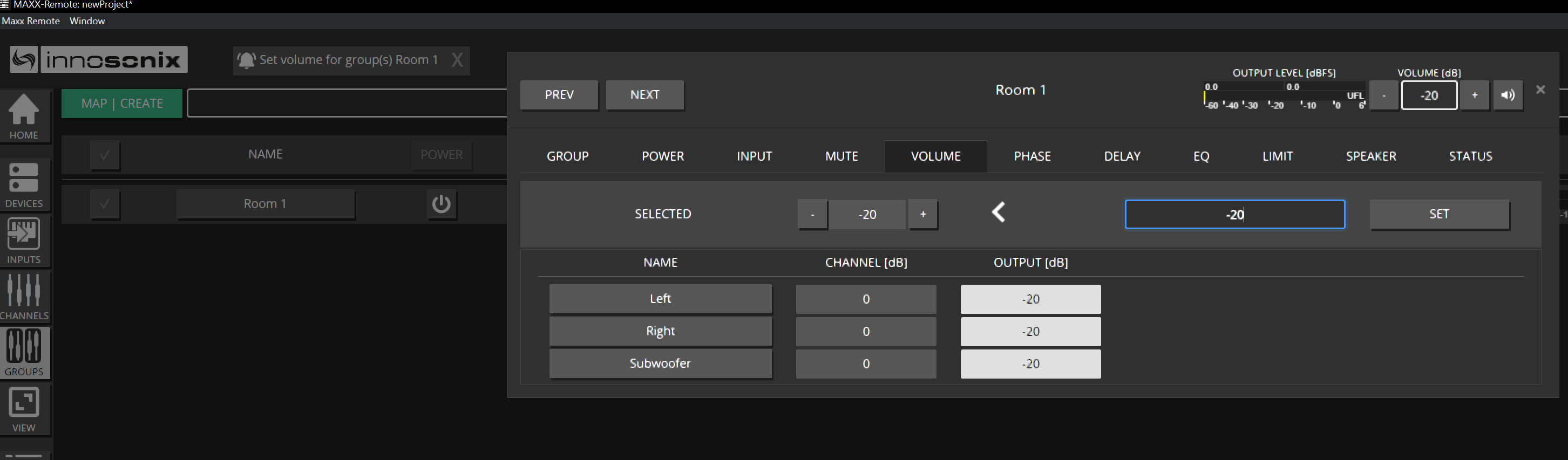
- Before doing anything else, let’s decrease the volume of our setup by -20dB. Navigate to GROUPS and click on the VOLUME field
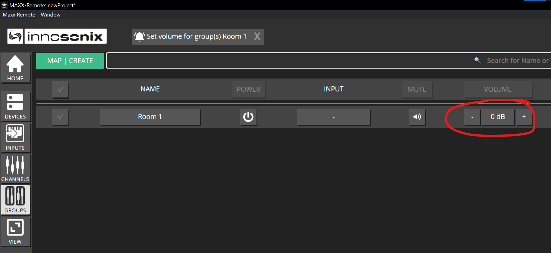
- Enter -20 and press ENTER or click on SET. This will update the Volume of all channels in that Group.
- Let’s increase the Volume of the Subwoofer by +6dB to give us a little boost. Navigate to CHANNEL and click on the VOLUME field of the corresponding channel.
Note
The CHANNEL overview always represents the final output results of those channels; that’s the reason why it already shows -20dB (from the group value we’ve applied before)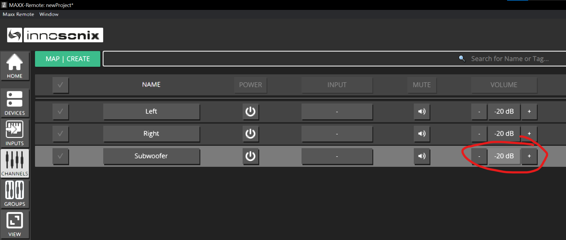
Type in 6 and press ENTER. The new OUTPUT result is shown. (-20dB from GROUP Room 1 and +6dB from the CHANNEL itself results in -14dB )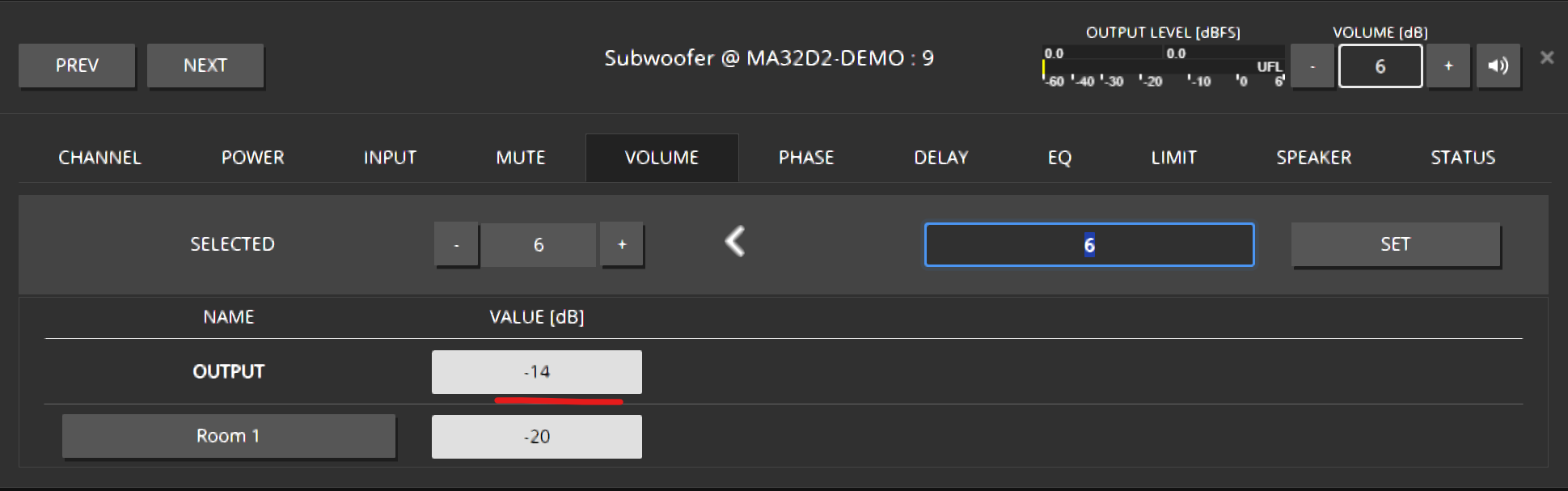
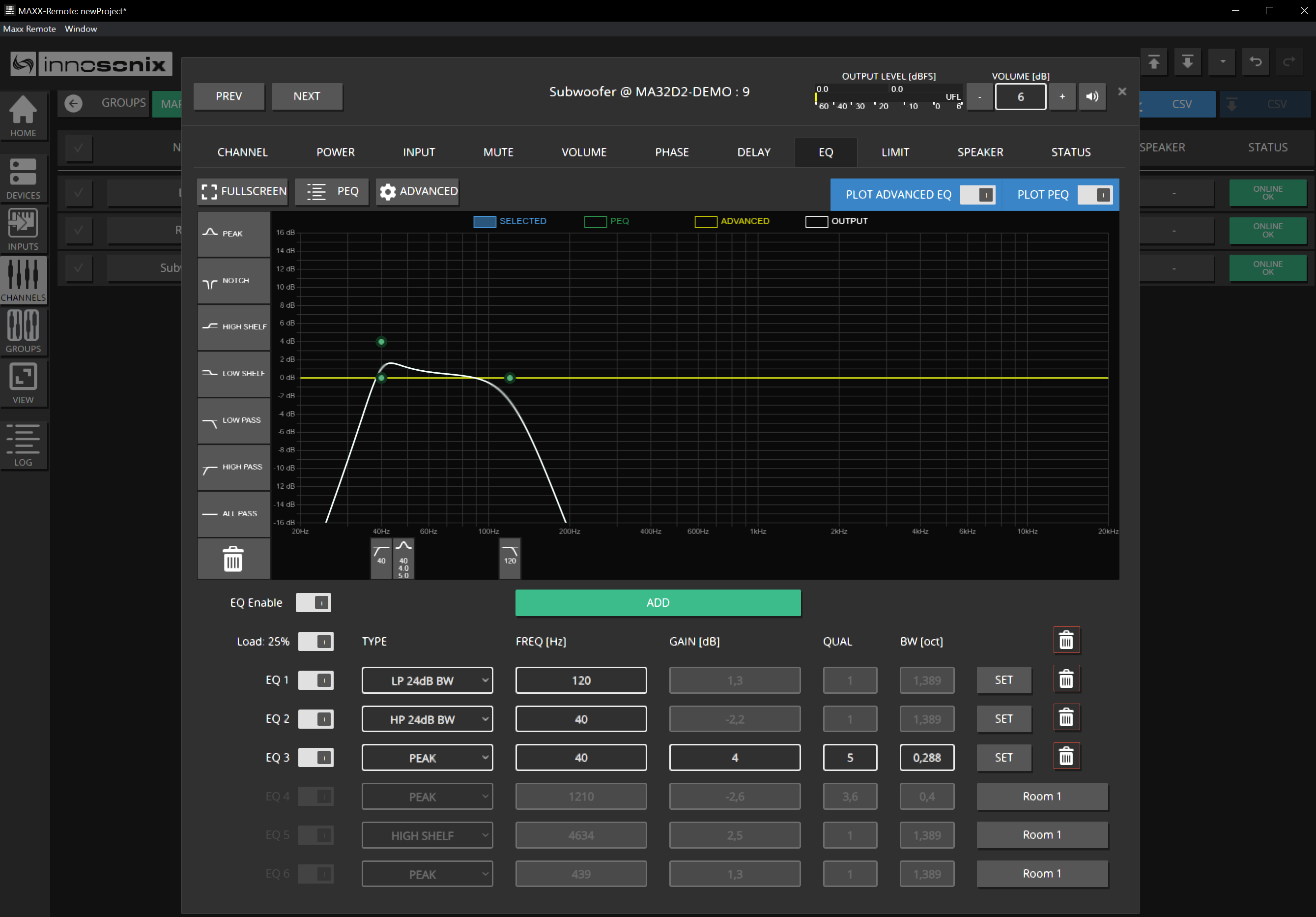
Adjusting the EQ for the Subwoofer
- Set an LP filter for the Subwoofer. Navigate to CHANNELS -> EQ Icon.
- Drag & Drop a LOW PASS filter into the EQ windows
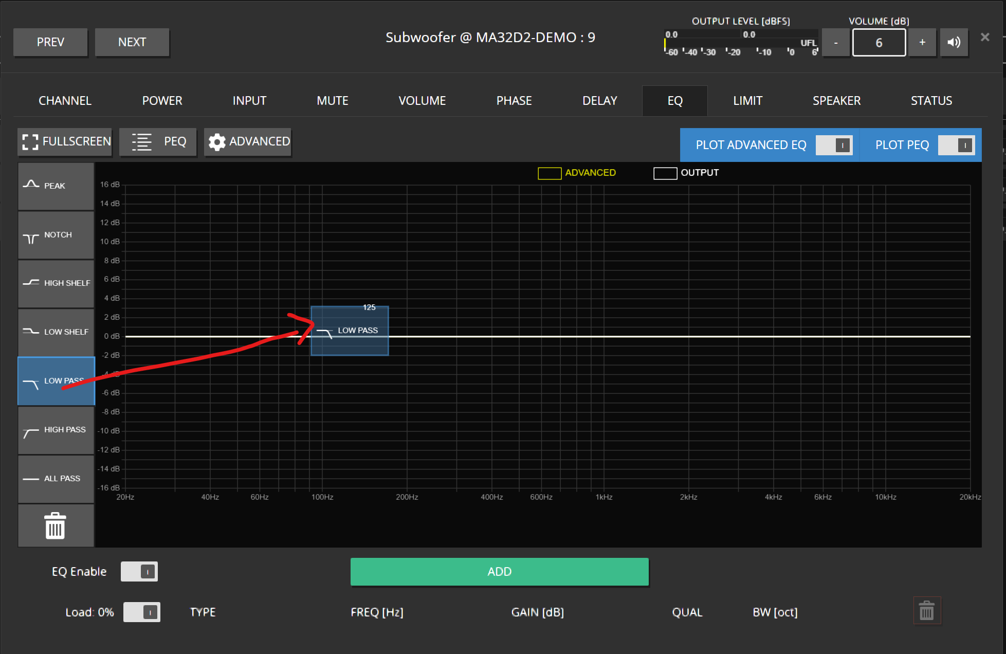
- Click on the blue dot or the blue rectangle on the lower part of the eq windows to select the filter. Click on the GEAR icon to open the Low Pass type editor. For example, select a 24dB Butterworth characteristic and confirm via OK.
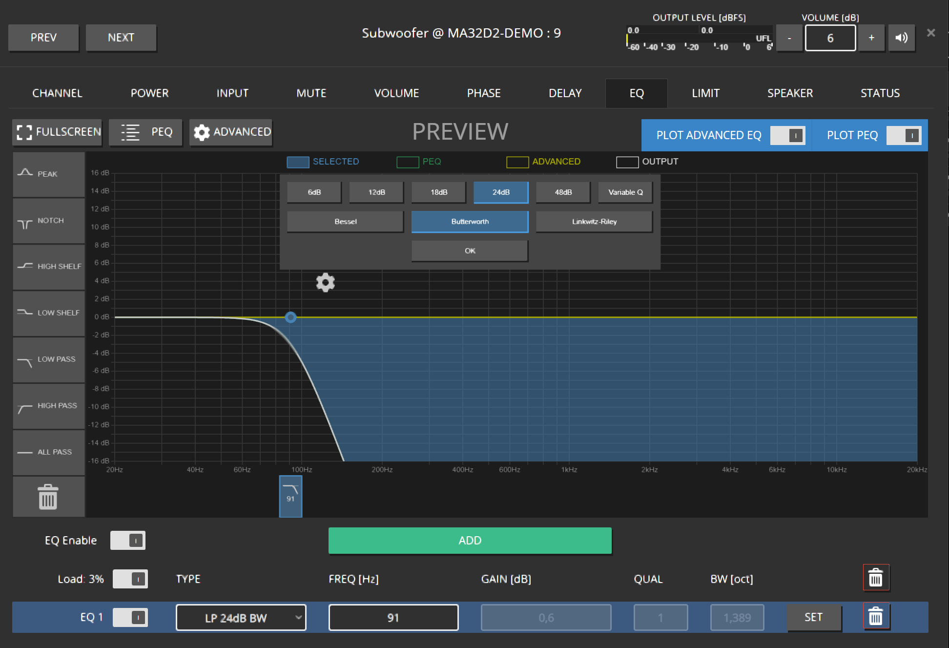
- The frequency can either be changed by dragging the blue dot or entering the desired frequency in the textbox below and confirming via ENTER / SET
- Add more filters as required.
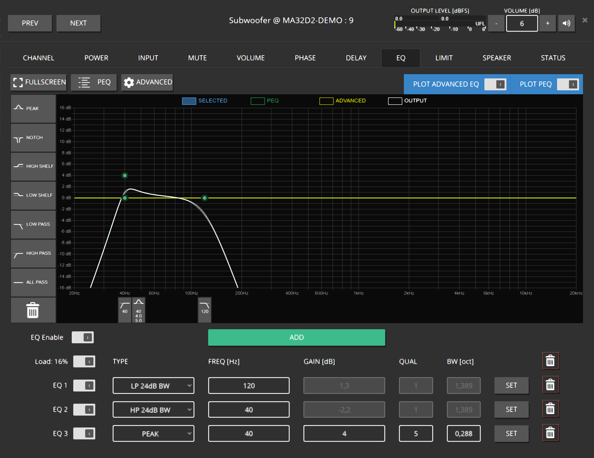
Adjusting the EQ for the Group
- Perform similar steps to add some overall EQs to GROUP Room 1, like:
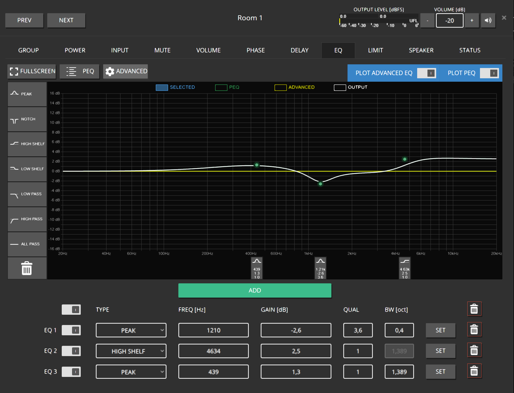
- Navigate back to the CHANNELS of GROUP Room 1 by using the ARROW button on the right, for example:

- Open the EQ of the channel Subwoofer again and take a look. This will indicate the summation of all EQs applied to that channel.
Creating some INPUTs
We can use different approaches to supply some music to those channels. But for now, assume a stereo source coming from a Dante Device / Dante Virtual Soundcard.
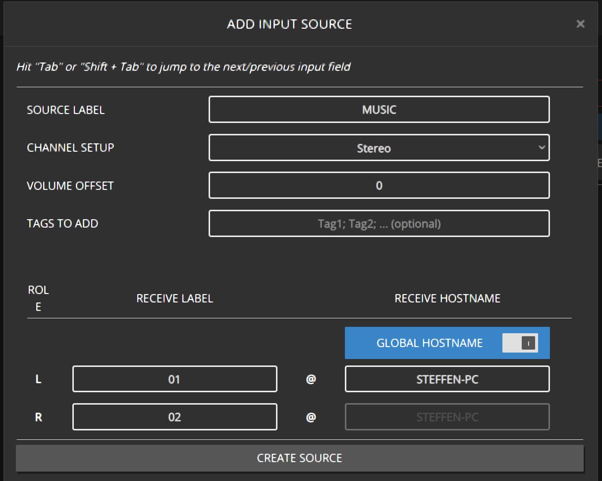
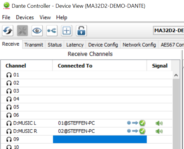
By using INPUTS in the Maxx Remote, we can specify MONO or STEREO Sources in the Dante network. The required information can be found in the Dante Controller, containing the HOSTNAME and the Transmit Channel name. A Dante Stream will be represented by that combination Transmit Channel@HOSTNAME.
In the example below, 01@STEFFEN-PC

- Click on INPUTS -> + INPUT SOURCES. Enter the required information.
- SOURCE LABEL: Just to identify that SOURCE in the Maxx Remote
- RECEIVE HOSTNAME: Hostname of the Dante Device
- RECEIVE LABEL: The Transmit Channel name
- Once the SOURCE is created, navigate to GROUPS -> INPUT and apply that SOURCE to that group, Room 1
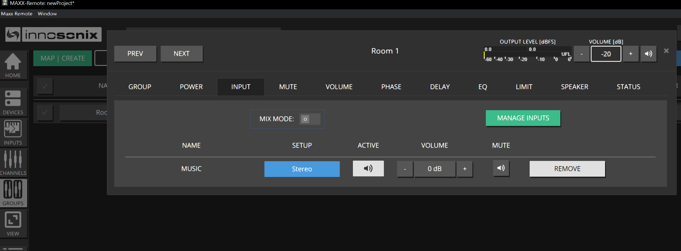
- All channels in that group will now assign that INPUT SOURCE based on their ROLE, like LEFT / RIGHT / MONO.
- The channel Left is now performing a downmix from STEREO to MONO by using both INPUTS
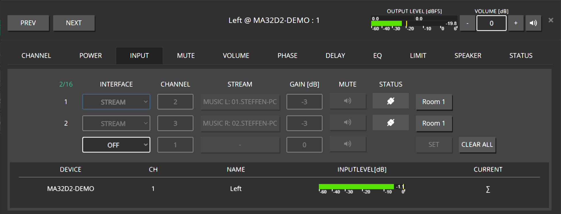
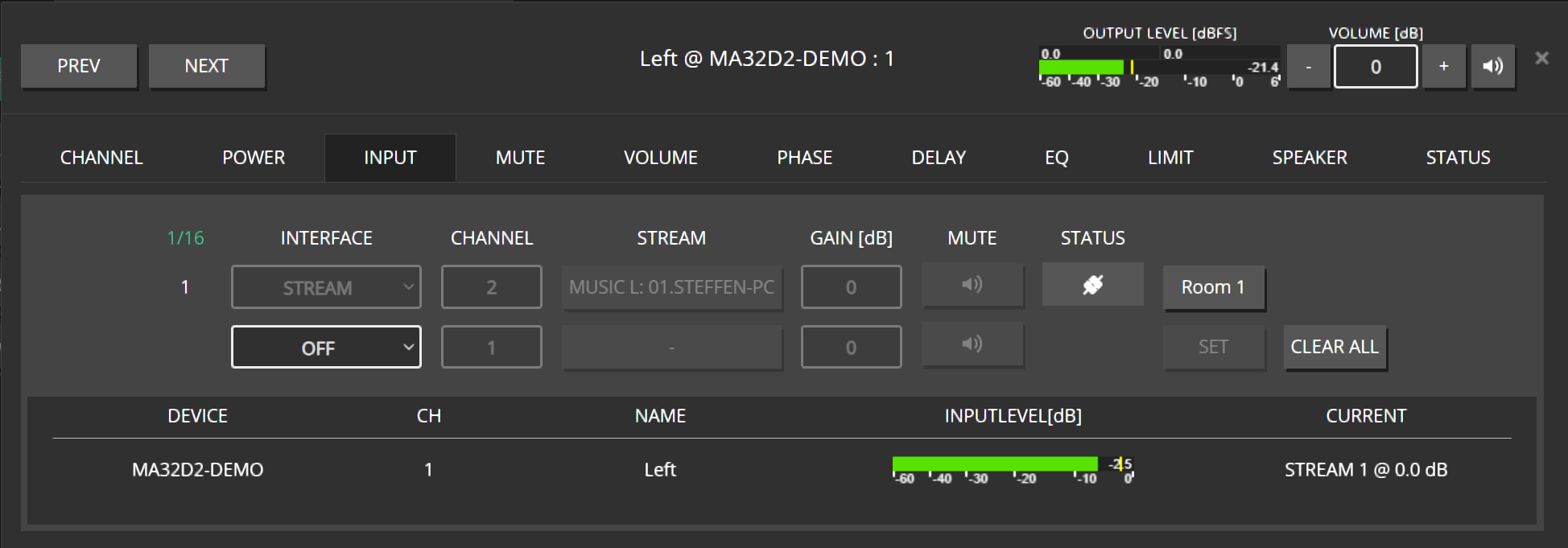
- Since this is not what we like to see here, change the CHANNEL ROLE to LEFT by clicking on CHANNEL -> ROLE -> LEFT
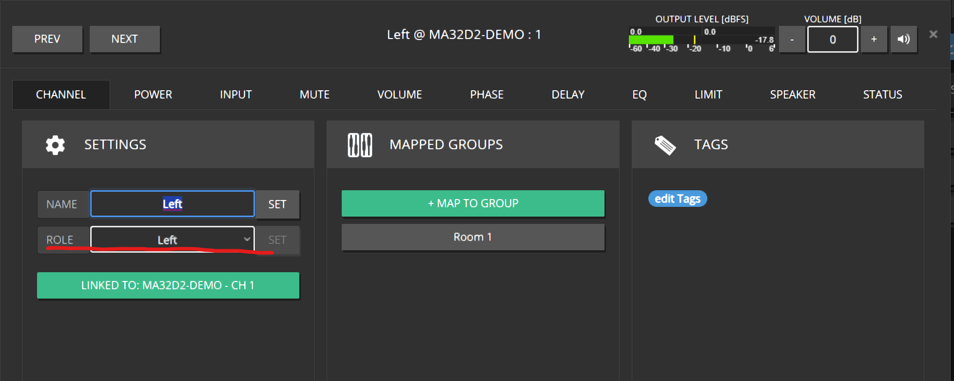
- The Channel now receives only the desired Left Channel of that INPUT SOURCE
- Looking at the Dante Controller should also indicate those dynamically assigned slots marked with a “D:”
- Repeat those steps for the channel Right.
- The Subwoofer is default set to MONO, so the downmix is performed correctly.
4 - Surround Input Sources
How to manage surround audio in Maxx Remote
For a basic explanation on how to handle Input Sources, please refer to the corresponding section in the Quick-Start chapter. Here we will have a more in-depth look on all the features regarding Surround audio.
Surround Channel Names
Since there is no uniform naming convention for the additional surround channels (The nomenclature will vary, depending on which resources you refer to), let’s quickly establish which designation in Maxx Remote refers to which speaker in a 5.1 and 7.1 surround setup:
5.1 Setup
 {width=300px}
- Center (C)
- Left (L)
- Right (R)
- Left Surround (Ls)
- Right Surround (Rs)
- Low Frequency Effect (LFE)
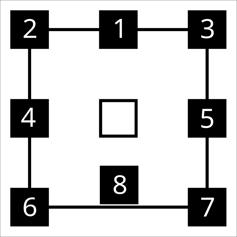
7.1 Setup
 { width=50% }
- Center (C)
- Left (L)
- Right (R)
- Left Surround (Ls)
- Right Surround (Rs)
- Back Surround Left (Bsl)
- Back Surround Right (Bsr)
- Low Frequency Effect (LFE)
Note
Of course the position of the LFE speaker(s) is not fixed within a surround setup and can vary for individual setups.Creating Input Sources
Creating Surround Input Sources works just as described in the Quick-Start chapter. Naturally, there are a few more channels requiring a RECEIVE LABEL for surround setups.
Additional Channel Roles
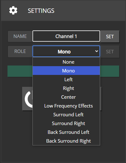
Since Surround Setups are not just limited to “Left” and “Right” channels, there are now a few more roles available that you can assign to a CHANNEL.
Selecting NONE will result in this CHANNEL not being provided any INPUT SOURCE related Dante Streams at all.
With MONO, a CHANNEL will usually be assigned to all the streams included in an INPUT SOURCE, but more on that later.
Group Output-/Channel Setup
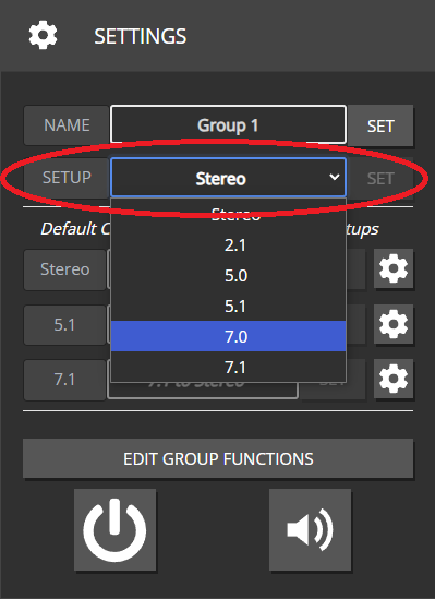
“Output-” or “Channel-Setup” is a new setting that has been added to the GROUP overview page. This setting should reflect the kind of speaker setup your GROUP is supposed to control. To guarantee a correct output, all channel-roles included in a surround setup need to be assigned to at least one CHANNEL mapped to this GROUP. Leaving out a necessary role or assigning a role that is not part of your selected output setup won’t throw any errors but will result either in a Dante stream not being assigned to any CHANNEL or in a CHANNEL not receiving any Dante stream.
Roles included in each Output Setup
Stereo: L, R2.1: L, R, LFE
5.0: C, L, R, Ls, Rs
5.1: C, L, R, Ls, Rs, LFE
7.0: C, L, R, Ls, Rs, Bsl, Bsr
7.1: C, L, R, Ls, Rs, Bsl, Bsr, LFE
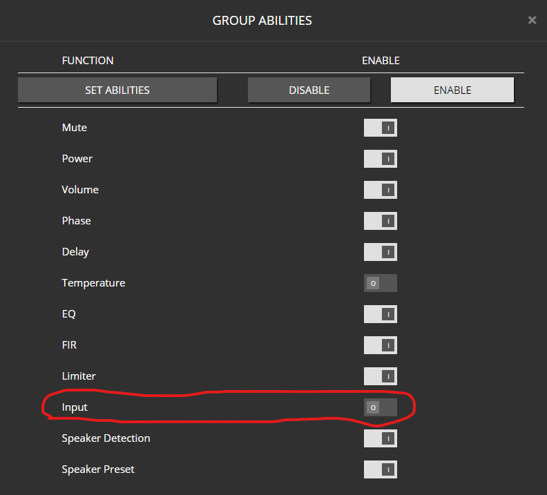
Disabling the “Input” ability for a GROUP will hide the Output-Setup and Crossmix Settings
Crossmixes
Definition
In real world scenarios, not always will the channel setup of a GROUP and the INPUT SOURCE you assign to it be an exact match. Either your speaker setup might have fewer channels available than your input source would require, or an INPUT-SOURCE requires fewer channels than your speaker setup provides. In the first scenario, you’d have to create a DOWNMIX of all the Dante streams to the available channel roles in case you want all the information included in the source material to be played back on the available speakers. In the latter scenario, you’d have to create an UPMIX in case you want to guarantee that all speakers will always be provided with a Dante stream.
For ease of communication, we combined those two scenarios under the term CROSSMIX.
The Crossmix Overview Page
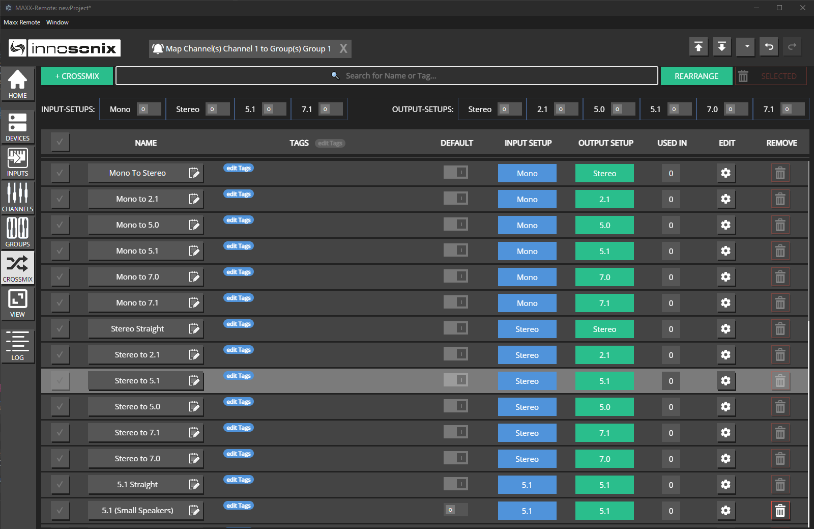 Maxx Remote will provide a set of predefined default crossmix strategies for all possible combinations of input- and output-setups that you can review and edit on the CROSSMIX page. Of course you can also define and add your own custom crossmix strategies.
 Besides the usual text search, at the top of the page you will also find a couple of filters, to quickly limit the displayed crossmixes to the desired input- and/or output-setups.
Note
All pre-defined crossmix strategies are fully editable, i.e. you can change or even delete them in case you wanted to.Assignment
Crossmix Strategies can be assigned at three levels to combinations of Input- and Output-Setups:
-
Global Default (lowest priority)
 Since for every combination of Input- and Output-Setup there must always be a global default to fall back to. It is not possible to un-default or delete a crossmix strategy currently assigned the role of default. Rather, you’d first have to assign another strategy as default for this combination of Input- and Output-Setup before being able to do either.
-
For all Input-Setups on a specific GROUP (medium priority)
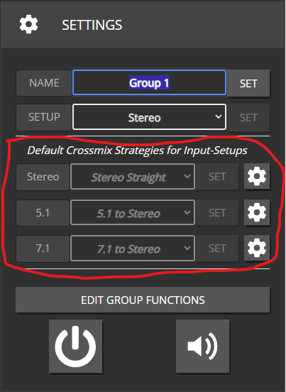
In case no specific strategy is assigned, the select box will display whichever strategy is globally assigned to this In-/Out combination.
-
For individual combinations of INPUT-SOURCE and GROUP (highest priority)
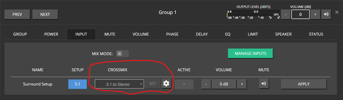 In case no specific strategy is assigned, the select box will display whichever strategy is applicable from either of the lower priority levels.
Programatically, a crossmix strategy is always used to determine which Dante streams should be routed to which output channels, not just in cases the input- and output setup do not match. Maxx Remote will check in reverse order (3. - 2. - 1.) to see, which strategy is applicable to the In-/Out combination at hand and distribute the Dante streams accordingly.
On all three levels, you can use the gear icon to open the EDIT view for the selected or applicable crossmix strategy.
The select boxes will only display the crossmix strategies befitting the Output Setup of the selected GROUP and whichever Input Setup is applicable.
Add-/Edit Crossmix
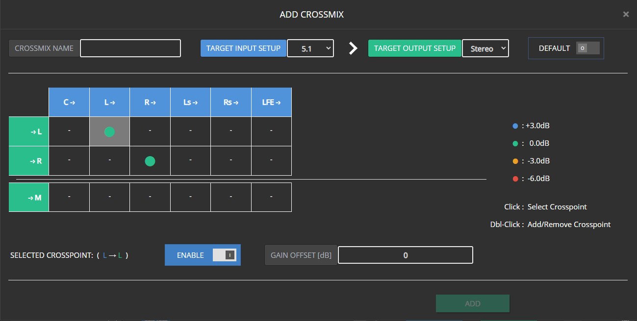
- The Crossmix configuration is displayed in a 2D matrix view, with the rows representing the available output channels, whereas the columns represent the expected input channels.
- You can set crosspoints, either by double-clicking a respective crosspoint, or selecting it via single-click and then clicking on the “Enable” switch.
- The “Gain Offset” input field will only be available for activated crosspoints and display the volume offset value for the selected crosspoint.
- For better and quicker readability, the most common offset values (0, +/-3, -6) are represented as color coded circles. All other values are displayed numerically.
- When disabling a crosspoint, its last Gain Offset value will be remembered when it is reactivated
- Enable the “Default” switch, in case you wish this Crossmix to be the new global default for the selected combination of Input- and Output-Setup
- To unlock the “Add” button, you first must assign a name to your new Crossmix.
- The Edit-Crossmix window offers both a “Save” and a “Save As New” function. While “Save” simply saves all changes made to the selected Crossmix (also name), “Save As New” will only be unlocked once you change the initially selected Crossmix’s name. All modifications will then be saved as a new Crossmix, while the Crossmix you initially selected will remain unchanged.

- Changing either the Input- or Output-Setup for a Crossmix assigned as global default is not possible, as doing so, would result in loosing the last fallback option for a specific combination of Input- and Output-Setup.

On the other hand, on none default crossmixes, the setup can easily be changed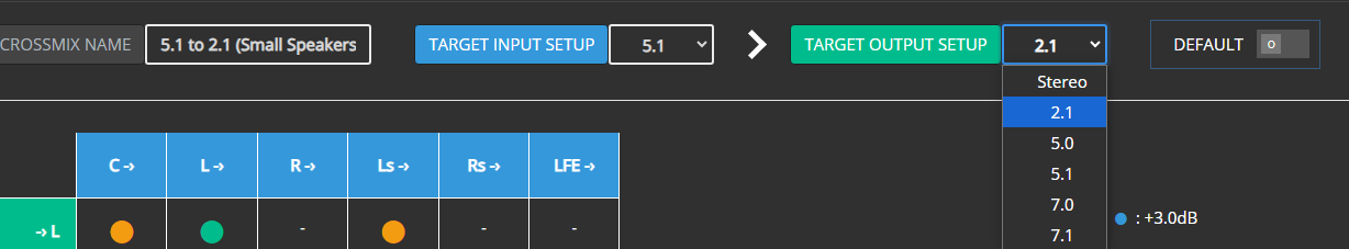
- Changing the Input- or Output-Setup for a Crossmix that is already assigned as GROUP or GROUP/INPUT specific Crossmix will result in this assignment being removed, and Maxx Remote updating all Dante stream assignments according to the next Crossmix in the hierarchy tree.
- Just as in the overview page, you can not un-default an existing Crossmix, but only select another Crossmix as Default instead.
Note
Crossmixing is the reason it is necessary to specifiy an Output Setup for each GROUP used for INPUT-SOURCE assignment. As an example, otherwise it would be impossible to realiably determine, wether a CHANNEL with the role “Left” would have to be assigned only the appropriate Dante stream, or any additional Dante streams transporting other Surround channels (i.e. a Surround to Stereo downmix)5 - Multi-Way Channels
Creating and managing Multi-Way Channels
In MAXX-Remote you can create multi-way channels. A multi-way channel is like a regular channel, which contains additional channel-objects (ChannelWays) that are hard-linked to their overlying channel (“parent-channel”). The main purpose of multi-way channels, is to represent an entire speaker in your installation using a single channel object, each channel-way representing one of the ways/drivers of that particular speaker, while the parent-channel will control the speaker as a whole.
Creating Multi-Way Channels
Please refer to corresponding section of the Quick-Start chapter for a general guide on how the “add-channels” dialog works.
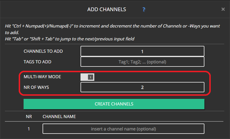
You can add multi-way channels, by enabling the MULTI-WAY MODE switch and selecting how many ways those channels shall include in the input field below. Currently, you can create 2-, 3-, or 4-way channels.
Switch to Multi-Way Mode
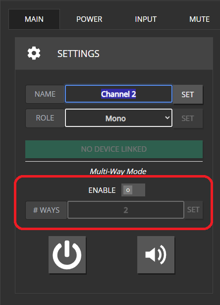
Alternatively, you can toggle multi-way mode for existing channels in the MAIN tab of the Channel-Edit Modal. When toggling the ENABLE switch, a popup will appear asking you to confirm the changes to be made. The same goes for changing the channel-way count on an existing multi-way channel. Set the desired number of ways and hit the SET button. A popup will appear, asking to confirm the changes.
When enabling multi-way mode, the target channel will receive the number of ways, set in the input field below. Note that you can also change the value of the way-count-input while multi-way mode is still disabled. That way, you can already set the desired number of channel-ways before enabling multi-way mode.
Editing the multi-way configuration of an existing channel will be prohibited in case the target channel is already linked to a device. Unlink such channels before editing their configuration. Further information in the Linking and Speaker-Device sections.
Note
Channel-Ways are always linked to their parent-channels. You cannot manually delete them, or assign them to another channel. They will only be removed when their parent-channel is deleted, when multi-way mode is disabled for their parent-channel, or when they become obsolete after reducing their parent-channel’s channel-way count.Naming-Convention
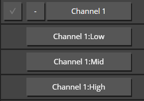
Channel-Ways don’t have individual, editable names. They are named using their parent-channel’s name and their designated channel-way-role. For the available multi-way configurations, the designated roles are as follows:
- 2-Way: Low, High
- 3-Way: Low, Mid, High
- 4-Way: Sub, Low, Mid, High
Linking Multi-Way Channels to Devices
Linking multi-way channels works mostly the same as with regular channels (Quickt-Start)
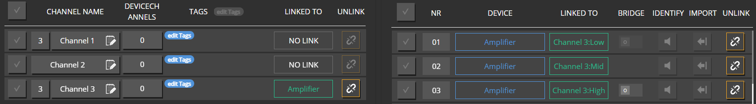
 In the Linking modal, multi-way channels have an additional box displaying their way-count.
 Additionally, the PROJECT CHANNEL side of the modal now offers a second PROJECT CHANNELWAYS tab which displays all the individual ways of multi-way channels.
 When linking multi-way channels in the PROJECT CHANNELS tab, you have to select the appropriate number of DEVICE-CHANNELS to unlock the LINK button (3-way channel -> 3 device-channels).
When linking via drag&drop:
- Dragging a multi-way channel will highlight the respective number of device-channels. (3-way channel -> 3 device-channels)
- When dragging device-channels over a multi-way channel, the number of device-channels needs to match with the number of channel-ways.
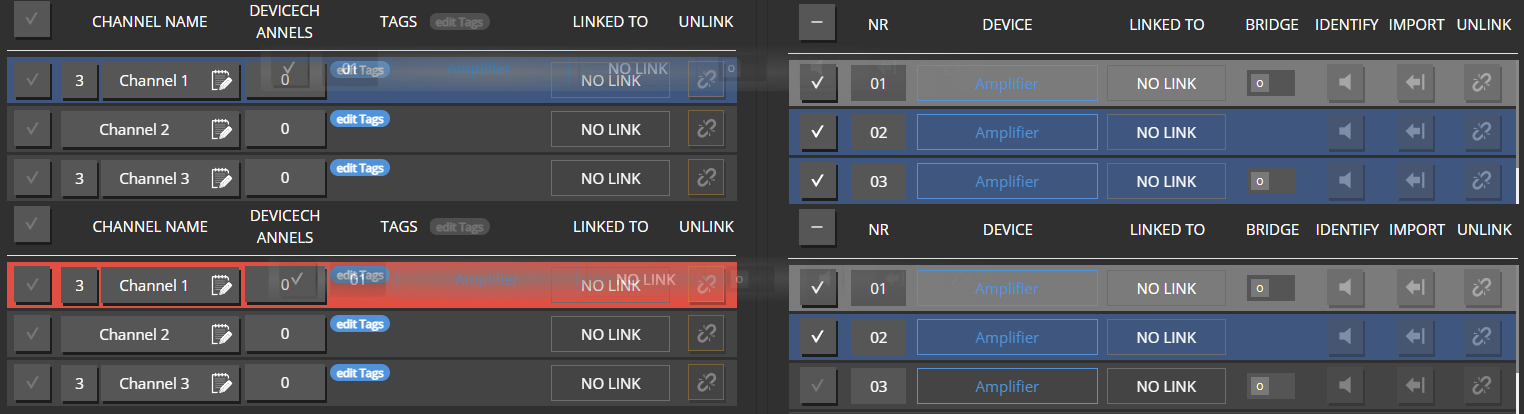
- Any additional device-channels will be applied to the next project-channel in line. If it is also a multi-way channel, the same rule applies as mentioned above.
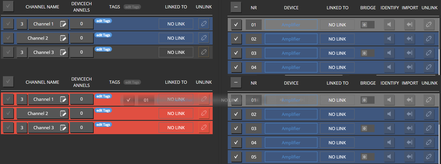
- When linking multi-way channels as a whole, device-channels are linked in the order they are listed to the individual channel-ways from low to high.
If you want or need to link individual channel-ways to different devices or not in the standard order as stated above, you can change to the PROJECT CHANNELWAYS tab. Here, linking channel-ways works just the same as with “regular” (i.e. non-multi-way) PROJECT-CHANNELS.
Changing the way-config for already linked channels was disabled, in order to help you NOT loose track of the connections between your channels and devices.
Linking individual channel-ways independent from each other has to be done intentionally via the PROJECT-CHANNELWAYS tab. You will be aware of loose links as long as the modal is active. Changing the config for an already linked channel would result in loose links (i.e. unlinked channel-ways or device-channels), while you potentially might not immediately be aware of them.
Speaker Devices
For future hardware, there will also be the possibility to add a predefined channel-way configuration. For example a 3-channel amplifier could be configured to behave like a 3-way speaker, propagating only one device-channel, while internally all 3 amplifier channels are assigned pre-defined roles (i.e low, mid, high).
For such devices, it is not possible to link individual channel-ways. A fitting multi-way channel needs to be linked to it as a whole.
When opnening the channel-linking modal for such devices, MAXX-Remote will already filter the PROJECT-CHANNEL side for multi-way channels with the corresponding number of channel-ways. The number of ways for a speaker device will be displayed next to the device’s name. (Same as with multi-way channels)
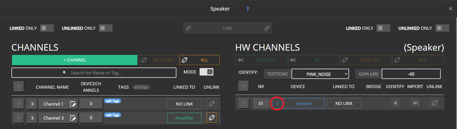
Linking multi-way channels and speaker devices behaves the same as linking regular project-channels and regular device-channels.
Speaker devices are another reasons we disabled changing the way-config for already linked channels. Since it is not allowed to link individual ways for speaker devices, changing the way-config of a channel already linked to a speaker device would result in such a condition. (i.e. either unlinked, additional channel-ways on the project-channel side, or one or more unlinked ways on the speaker device side)
Data Hierarchy
The relation between the data of a channel-way and its parent-channel is pretty much the same as between a regular project-channel and a group. For data with limited ressources (i.e. Limiters, FIR, EQ, Speaker Detection) on the hardware side, a channel-way’s own settings will always take precedence over its parent-channel’s. As long as ressources are available and the endresult is within the allowed constraints, channel-ways will combine their parent-channel’s data with their own.
Note that just as well a parent-channel’s data can already be the accumulated result of its own data, and that of the groups it is mapped to.
Differences between regular Channels and Multi-Way Channels
Both in the channel-overview page, and the channel-edit modal, there are a few differences between regular project-channels, channel-ways and their parent-channel.
 In the overview page:
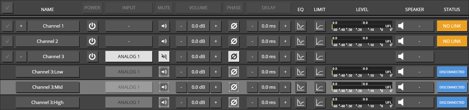
- Channel-Ways are excluded from selection. (all data-changes that should affect all ways of a multi-way channel, can be performed on the parent-channel)
- Channel-Ways in general do not have an individual power control.
- The INPUT button for channel-ways is read-only (all input patches are adopted from the parent-channel)
- When extended, a parent-channel will not display a level-meter or status-box.
- The level-meter of a parent-channel will display the group-level of it’s channel-ways
- the STATUS box of a parent will display the combined status of its chanhnel-ways
 The edit modal for channel-ways has no POWER and INPUT tabs (all input patches are adopted from the parent-channel)
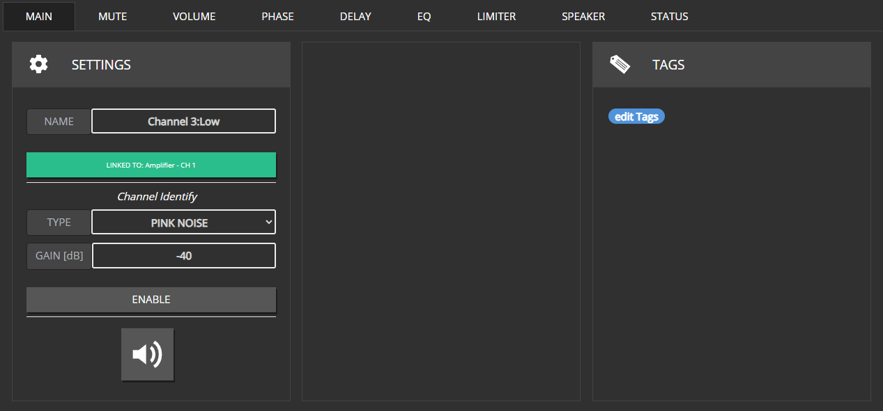
The MAIN tab of channel-ways:
- will not show any group related information.
- has a read-only name field.
- has no output-setup related channel-role setting.
- excludes the multi-way configuration section.
- has no power control.
 The edit modal for parent-channels:
- Will not include speaker detection controls in the SPEAKER tab. Since detection settings/values will vary quite a bit between individual channel-ways - depending on their role and the connected type of driver/speaker - a one-for-all approach will not yield any useful results. Thus, these controls are not displayed in the first place.
- Will display their channel-ways’ status data in the STATUS tab (Just as groups will for all their mapped channels)
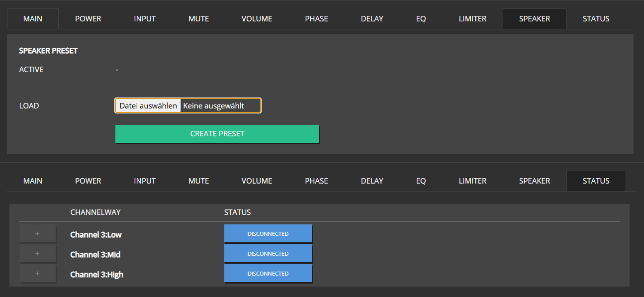
6 - Speaker Presets
Speaker Preset creation and usage
As of version 1.13.0 MAXX-Remote offers the ability to create Speaker-Presets for single- and multi-way channels. For an in depth look on Multi-Way Channels, please refer to the respective Chapter of this guide. Previously, speaker presets could only be created and edited directly on our MAXX devices. This feature has now shifted into MAXX-Remote.
Creation
In order to create a speaker preset, simply take a regular or multi-way channel and apply all the settings you want your speaker preset to include. Data fields currently included in a preset are:
- Volume
- Phase-Invert
- Delay
- EQ
- FIR
- Limiters
Once finished, open the SPEAKER tab of the channel edit modal (parent-channel for multi-way channels) and hit the CREATE PRESET button. A popup will appear where you can add some meta data to your preset. Additionally you can also set a password for your preset in case you want to restrict the possibility of editing it to authorized users only.
Note
Presets are encrypted and encoded. The settings of your preset will be never be readable as plain text. Neither when exported as a file, nor when stored in a project file or MAXX-Remote’s temp datastore.Editing
In order to edit a speaker preset, go to the SPEAKER tab of a channel that has the desired preset applied to it and hit the EDIT button. In case your preset is password secured, your will be prompted to enter the password. Naturally, editing will only be unlocked with the correct password. Once in Edit Mode, the channel overview will only display the channel you chose to edit the speaker preset, as well as channel objects representing the preset’s settings.
Presets have an internal revision counter. Every time you edit a preset, this counter will increment. This is necessary so it is possible - when exporting a preset to file - to determine which of two seperate preset files with identical preset names and IDs is more up to date in terms of its settings.
Applying Presets
In order to apply a speaker preset to a channel or group, got to the SPEAKER tab in the edit modal, click the Select file button and chose a ‘.spkr’ file you want to apply to your target channel or group.
Note that the way-configuration of a speaker preset and the target channel need to match. You cannot load a preset, created for 2-way channels into a single- or 3-way channel.
When applying a speaker preset to groups, channels that are mapped to this group will adopt the group’s speaker preset, unless they have their own speaker preset assigned to them. In case there are multiple groups with speaker presets for a channel, it will adopt the preset of whichever group has been mapped to it first. Such conditions however can be considered bad design and should be avoided.
In case the way-configuration of a group’s speaker preset does not match with any of the channels it is mapped to, the preset will be ignored by mismatching channels.
Legacy Presets
MAXX-Remote and all Innosonix devices are still compatible with presets that have been created on MAXX-Devices (file extension ‘.speaker’). However, these presets can not be edited in MAXX-Remote. Also, new presets will always take precedence over legacy presets. I.e. legacy presets will be removed in case a new preset is applied to a channel or group. Channels will always prefer new presets over legacy presets, even when the legacy preset is directly applied to the channel, and the new preset is adopted from a group.
7 - GUI
Walkthrough the different GUI pages
fdf
7.1 - GROUPS
All Groups to manage your Project
7.2 - SIG-PATH
Signal Path for all your project channels.
7.3 - VIEW
Custom creation of simple overview pages with controls / status
8 - API
Different API entry points are available to the maxx-remote-server
Depending on the level of integration or use cases Maxx Remote is intended to be use, there are several entry points to get data or views out of the server.
8.1 - GROUP-SIGNAL-PATH
The SIG-PATH view form the GUI as standalone web page but scoped per group-id
GROUPS are addressed via an internal UUID (unique id), like 36875a19-8203-4647-9760-303ffd3c8f8f
To get a scoped view of that group in the SIG-PATH, the group-id could be called with the http://{server}:8000/group-signal-path/{uuid} url, e.g. http://localhost:8000/group-signal-path/36875a19-8203-4647-9760-303ffd3c8f8f
8.2 - REST-API
API calls to the maxx-remote server
Similar approach as the HTTP api like used by MAXX-CONTROL but this time, controlling the server itself.
This is intended as main entry point to the maxx-remote system from an third party control perspective like media controls, etc.
Functionality is more focused on end user control than really setup the system.
The full open-api documentation of that api is shipped within each Maxx-Remote system, and can be found on the lower left HOME section.
Or through that url http://localhost:8000/api-docs/ when a maxx-remote is running on your system.