Always start with IDFM (install) to set IP and firmware on all devices.
On this site, Maxx Control docs focus on the device REST API and third-party plugins; the full on-device UI manual is published separately (see downloads).
These tools apply to the MAXX family including micro MAXX (same Maxx Control webpage/API and full Maxx Remote support).
Basic device setup in the network → IDFM (install)
Single device without much need to constantly change settings of multiple channels → Maxx Control
Head start without any additional installation? → Maxx Control
More than one device? Recommendation → Maxx Remote
1 - IDFM
IDFM (Innosonix Device and Firmware Manager): discover amplifiers, set IP and hostname, and update firmware before Maxx Control or Maxx Remote.
IDFM (Innosonix Device and Firmware Manager) is a desktop Electron app for bringing amplifiers onto a working network plan and keeping firmware current. Use it before Maxx Control or Maxx Remote. That workflow includes micro MAXX and other MAXX amplifiers.
When to use which tool
Need
Tool
Discover amps, set IP / hostname, update firmware
IDFM (this section)
One amplifier — DSP, routing, device settings in the browser
NSIS installer — choose install directory; desktop / Start menu shortcuts available
Linux
idfm-….AppImage
Make executable, then run (no separate installer)
macOS
idfm-….dmg
Universal build; open the DMG and install the app as usual
IDFM may offer an in-app update when a newer tool version is published on the download service.
First launch
Start IDFM.
Open the DEVICES page (default).
Check UDP STATUS (top right).
Confirm devices appear, or that the status does not show UDP blocked / port unavailable.
Expected result
The device table loads. Online count updates as amps answer discovery. If nothing appears yet, continue with Discover and IP (same L2 segment, or add/scan).
Firewall and UDP status
Automatic discovery uses UDP 9453. The PC firewall must allow IDFM to send and receive that traffic on your control network.
Use UDP STATUS to see whether discovery sockets are healthy on local interfaces.
If another IDFM instance is already running, you may see a port already in use message — quit the other instance.
Windows: if devices never appear, open HELP in IDFM. The FAQ can re-apply Windows firewall allow rules for the app, or (last resort) temporarily disable the firewall profile while diagnosing. Prefer fixing rules over leaving the firewall off.
macOS
On first use, grant local network access if the system prompts. Discovery needs it.
Use IDFM to find Innosonix amplifiers (UDP discovery or add/scan), then set STATIC-IP or DHCP, hostname, and identify the physical unit.
Goal / when to use
Put every amplifier on the site IP plan: discover (or add) devices, set STATIC-IP or DHCP, name them, and confirm which physical unit is which.
Prerequisites
IDFM installed with healthy UDP STATUS when you expect automatic discovery
PC on the same L2 segment as the amps for UDP broadcast, or known amp IPs / reachable routed subnet for add/scan
UDP discovery (preferred)
On the same switch / VLAN, IDFM discovers amps with UDP broadcast on port 9453 (255.255.255.255).
Open DEVICES.
Wait for rows to appear (hostname, model, firmware, IP, status).
Filter or sort the table if you have many units.
UDP discovery still works when the amp’s configured IP is on a different subnet than the PC — as long as they share the same broadcast domain. That is how you recover “wrong IP” units without serial console access.
Unicast HTTP may fail, but UDP discovery can still list the amp and accept a new IP configuration.
Expected result
Amps show as online in the list. You can open IP / hostname dialogs from the row.
Set IP (STATIC or DHCP)
Click the IP cell for the device.
Choose TYPE:
STATIC-IP — enter IP, subnet, gateway
DHCP — device takes an address from the DHCP server
Click SET.
Optional on DHCP: NEW DHCP LEASE to renew.
After a STATIC change, wait a few seconds for the list to refresh. After DHCP, the old address may go offline until the amp reappears with the new lease.
Tip
For installed systems that Maxx Remote will manage, prefer planned STATIC-IP (or reserved DHCP) so discovery and linking stay stable.
Hostname and identify
Action
How
Hostname
Click the hostname cell → enter a unique name → SET HOSTNAME
Identify
Use IDENT on the row so the physical amp signals which unit you selected
Location
Optional site text via the location cell (stored on the device when reachable over HTTP)
Device page
Use the external/page control to open the amp’s web UI (Maxx Control) once the IP is reachable
Add by IP or subnet scan (routed networks)
Routers do not forward UDP broadcast. If the PC and amps are on different routed VLANs, use + above the device list:
Add by IP — enter a known amplifier IP (device must answer ping / HTTP).
Subnet scan — enter the first three octets of the target /24 (for example 192.168.99) and scan. IDFM probes live hosts via the device HTTP REST API.
For a successful update, the PC and amplifier should share a reachable unicast path on the same subnet (loader / update traffic is not the same as UDP discovery-only)
Internet on the PC to fetch images from Innosonix, or.inx files copied from another machine
Check for updates
Start IDFM with network access.
Open the FIRMWARE tab. A red badge can indicate newer images are available to download.
The FIRMWARE UPDATES control (when shown) summarizes devices that have a newer release than they are running.
IDFM compares discovered device versions against the firmware catalog and images you have stored locally.
Download firmware (online)
Open FIRMWARE.
Download the images you need for the models on site.
Files are kept on the PC so you can update later without internet.
Local store (created by the app):
~/Innosonix/IDFM/firmwareStorageFolderIDFM/
(On Windows, under your user home directory with the same folder names.)
Import firmware (offline)
When the commissioning PC has no internet:
On a connected machine, download .inx files from the downloads page (or download them inside IDFM and copy from the store above).
Transfer via USB or similar.
In IDFM FIRMWARE, import the .inx file(s).
Update devices
On DEVICES, select the units to update (or open update from the toolbar).
Choose UPDATE DEVICES / the firmware update flow.
Confirm the target image per model.
Start the update and wait until each unit finishes and returns to a running state.
You can update multiple devices in one session when images are already local.
Expected result
Device firmware columns show the new version. Amps reboot as required and come back online in the list.
Important
Do not power-cycle amps mid-update. If a unit is already in the firmware loader and not on the same subnet as the PC, connect the PC directly (or fix routing) before retrying — see Troubleshoot.
Manual bootloader fallback (MAXX²)
On MAXX² amplifiers with a front-panel display (for example MA32/D², MA32/LP², and similar models), you can force the device into bootloader mode from the front panel. Use this when you want more manual control over the update workflow, or as a recovery path when a normal update does not start.
Warning
Use this only when needed. Power the device off before you start, follow site electrical safety rules, and keep holding ESC + OK until the bootloader is active.
Steps
Power the amplifier off.
Hold ESC + OK on the front panel.
Power the amplifier on while keeping ESC + OK held until it enters bootloader mode.
In IDFM, select the device and run the firmware update with the correct .inx image (see Update devices above).
Expected result
The amp appears ready for an IDFM update from bootloader / loader state. After the update finishes, it returns to a normal running status.
Update warning about subnet / reachability; device stuck in loader; progress never finishes.
Steps
Put the PC on the same subnet as the amp management IP (unicast path for loader TCP 9454 / update). UDP discovery alone is not enough.
Download or import the correct .inx for that model first (FIRMWARE tab).
If the unit is already waiting in the loader and still unreachable from your current network, connect the PC directly to the amp (or fix routing) and retry.
Do not power-cycle during the update unless support instructs you to.
If you need a more manual recovery path on a MAXX² front-panel amp, force bootloader mode with ESC + OK at power-up, then update from IDFM — see Manual bootloader fallback.
Expected result
Update completes; device returns to a running status with the new version.
Maxx Control (MaxxControl): per-amplifier web UI and open REST API. Control one amp in the browser; use Maxx Remote when you need multi-amp projects.
Maxx Control (also written MaxxControl) is the control surface built into every Innosonix amplifier: a browser web UI plus an open REST API on the device. Use it for one amplifier when you want local control with no desktop install, or when a media-control / home-automation system should talk to a single amp. That includes micro MAXX — same webpage and API as other MAXX models. For many amplifiers, rooms/groups, and offline projects, use Maxx Remote instead.
If an amplifier is linked and owned by Maxx Remote, treat Maxx Remote as the source of truth. Day-to-day edits in Maxx Control (UI or REST) on the same channels can create an Out of Sync state.
Access (brief)
Set a reachable IP (and hostname) with IDFM, or use the address shown on the device front panel.
Open the UI in a browser: http://<ip>/ (many networks also accept http://<hostname>.local/).
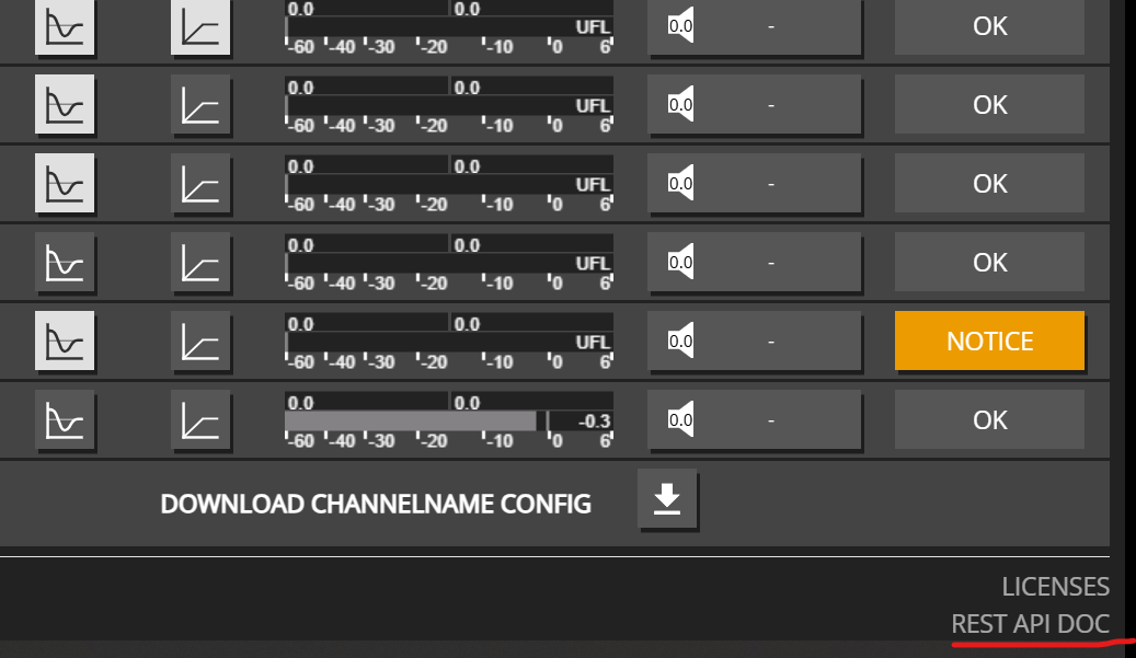
On-device REST documentation (full OpenAPI / Swagger): OVERVIEW page → REST API DOC (lower right), served as http://<ip>/…/doc/maxx_rest_api.html.
HTTP is on port 80. The API base path is /rest-api.
What this docs site covers
This section focuses on REST API usage for integrators and third-party systems, plus third-party plugins that wrap that API.
UI / operator manual
The full Maxx Control UI operator manual is published separately (device / product manuals on the Innosonix downloads page and related product pages). This site does not walk through every screen of the on-device UI.
Start here
REST API overview — auth, hierarchy, OPTIONS, where the full schema lives
REST API use cases — mute, volume, status, save, EQ, and more under Common use cases
Maxx Control REST API on each Innosonix amplifier: auth, hierarchy, OPTIONS, AES67 / SDP subscribe, and where the full OpenAPI lives.
Every amplifier exposes a hierarchical JSON REST API used by Maxx Control itself and by third-party systems. Prefer this API for single-device integration. For project-level multi-amp control, use the Maxx Remote HTTP API instead.
Base URL and transport
Item
Value
Scheme / port
http:// on port 80
Base path
/rest-api
Example
http://${IP}/rest-api/settings/channel/1/dsp/mute
Methods you will use most: GET (read), PUT (write / partial update), OPTIONS (allowed ranges and constraints), plus POST / DELETE on a few resources (for example EQ bands).
Authentication
Write operations that change settings require an API key in the HTTP header:
Header
Default value
token
f4005bf8507999192162d989d5a60823
Defined in OpenAPI as ApiKeyAuth (token in header). GET and most OPTIONS calls do not require the token. Most PUT (and many DELETE) calls do — check the on-device OpenAPI for each path; a few DELETE endpoints are unauthenticated in the schema.
The tree is organized under /settings (configuration), /status (live state), /info, /preset, and helpers such as /speakerpreset. Channel resources nest DSP blocks (volume, mute, EQ, FIR, limiters, …); device resources cover master mute/volume, Dante, network, and more.
You can:
PUT a deep leaf, e.g. …/settings/channel/1/dsp/mute
PUT a parent with a partial JSON object, e.g. …/settings/channel with an array of channel objects
PUT…/settings with a larger tree when you need a wide update in one call
Partial updates are the normal pattern: send only the fields you want to change.
OPTIONS = parameter constraints
OPTIONS on a resource returns the allowed parameter space for that property (min / max / step / unit, enums, string lengths, and similar). Use it when building UIs or validating values before PUT — especially for volume, delay, limiters, and names.
Exact response fields vary by resource; see the on-device OpenAPI schemas (for example NumberOptions).
Full OpenAPI (source of truth)
This site documents common integrator patterns. The complete, firmware-matching schema is on the device:
Open Maxx Control → OVERVIEW
Click REST API DOC (lower right)
That opens the Swagger UI for maxx_rest_api.html (generated from the device OpenAPI). Always trust the on-device docs for path lists and schemas for your firmware version.
Third-party plugins (Q-SYS, Loxone, …) use this same API against one amplifier each — see Third-party plugins.
2.1.1 - Maxx Control REST: Set channel names
Maxx Control REST: get and set channel names for zones, UI labels, and home-automation integrations.
Use the Maxx Control REST API to get and set channel names so zones and automation UIs stay readable. Names can contain alphanumeric characters, spaces, and special characters.
Tip: Use descriptive channel names to make your system easier to manage, especially when integrating with home automation systems or control interfaces.
2.1.2 - Maxx Control REST: Control device mute and volume
Maxx Control REST: set device master mute, master volume, and startup mute for one Innosonix amplifier.
Use the Maxx Control REST API to set device-level master mute, master volume, and startup mute on one amplifier. These controls affect all channels globally — useful for emergency mute, master volume, and safe startup behavior.
Device Mute
The device mute acts as a master mute that affects all channels, regardless of individual channel mute settings.
Use Case: Enable startup mute to prevent audio from playing immediately after power restoration, giving you time to verify system status before audio begins.
Complete Device Control Example
Here’s an example that combines multiple device-level controls:
# Set device to start mutedcurl -X 'PUT' http://${IP}/rest-api/settings/device/dsp/startupmute \
-H 'Content-Type: application/json'\
-H 'token: f4005bf8507999192162d989d5a60823'\
-d '{"value": true}'# Set master volume to a safe levelcurl -X 'PUT' http://${IP}/rest-api/settings/device/dsp/volume \
-H 'Content-Type: application/json'\
-H 'token: f4005bf8507999192162d989d5a60823'\
-d '{"value": -10.0}'# Unmute device when readycurl -X 'PUT' http://${IP}/rest-api/settings/device/dsp/mute \
-H 'Content-Type: application/json'\
-H 'token: f4005bf8507999192162d989d5a60823'\
-d '{"value": false}'
2.1.3 - Device Information
Examples for retrieving device information
Getting Device Information
The device information endpoint provides details about your amplifier model, available channels, installed options, and hardware features.
Get Device Information
Retrieve all device information with a simple GET request:
model_name: The amplifier model (e.g., MA32D, MA32LP, MA24D2)
channel: Number of available channels (16-32)
options: Array of installed options:
IF1, IF2, IF3: Interface options
D1, D2, D3: Dante options
M1: Additional options
psu_fan: Whether PSU fan is installed
housing_fan: Whether housing fan is installed
This information is useful for:
Verifying device capabilities before making API calls
Determining available channel count
Checking installed hardware options
Building device-specific automation logic
Status snapshot
Read calls do not need the token.
GET /status returns the full status tree (channels, device, interfaces, save state, syslog summary).
curl "http://${IP}/rest-api/status"
Health-oriented errors
GET /status/error aggregates channel and device errors with severity and status_flags (error / warning / ok).
curl "http://${IP}/rest-api/status/error"
Narrower reads are available, for example GET /status/device or GET /status/channel/{channel_id} — see on-device OpenAPI.
2.1.4 - Maxx Control REST: Enable or disable EQ
Maxx Control REST: enable or disable channel EQ (eqenable) with single-channel and multi-channel PUT examples.
Use the Maxx Control REST API to enable or disable channel EQ (eqenable) — bypass the whole equalizer for testing or mode changes while keeping filter settings intact.
Enable EQ for Multiple Channels
Enable the equalizer for multiple channels in a single request:
Note: When EQ is disabled, all equalizer settings (filters, gains, etc.) are bypassed, but the settings themselves are preserved. Re-enabling EQ will restore the previous equalizer configuration.
2.1.5 - Mute Control
Examples for controlling channel and device mute states
Channel Mute Control
Mute control allows you to silence individual channels or the entire device.
Note: Device volume acts as a master volume control affecting all channels. Individual channel volumes are relative to this device volume setting.
2.1.7 - Maxx Control REST: Device grouping
Maxx Control REST: create device groups, assign channels, then mute, solo, and set group volume on one amplifier.
Use the Maxx Control REST API to group channels on one amplifier, then mute, solo, or trim volume for that set. This is the same grouping Maxx Control’s GROUPS page uses.
These are device groups (16 slots on the amp). They are not Maxx Remote project groups. For rooms across many amplifiers, use Maxx Remote.
How grouping applies
A group only affects audio when enable is true. Then:
Control
Effect on assigned channels
Mute
Mutes every assigned channel (on top of channel mute).
Volume
Adds to each assigned channel. If a channel is in several enabled groups, those group volumes sum.
Solo
Keeps assigned channels open and mutes other channels that belong to some enabled group. Channels that are in no group stay untouched.
assign_id is the amplifier channel number (1…channel count). group_id is 1…16.
assign_id is the channel. value: true adds the channel; false removes it. OPTIONS on /assign reports [MIN, MAX, STEP, UNIT] for assign_id (max is the device channel count).
Read a single assignment with GET /settings/device/grouping/groups/1/assign/1 → { "assign_id": 1, "value": true }. Assignment is write-only on the collection path — there is no PUT on /assign/{assign_id}.
Enable the group
Mute, solo, and group volume are ignored until the group is enabled:
Group volume uses the same range as channel volume: -72.0 dB to +24.0 dB, step 0.1 dB. It adds to each assigned channel; it does not replace channel volume.
You can PUT several groups in that same array (for example a Foyer group and an All Subs group).
Note
A channel may belong to more than one enabled group. Mute from any of those groups mutes the channel. Volumes add. Avoid stacking large group trims on the same channels.
2.1.8 - AES67 / SDP subscribe
Maxx Control REST: subscribe a channel input to an AES67 / SDP stream (source_id 25) by PUTting sdp_text or rtp_flow.
Subscribe an amplifier channel DSP patch to an external AES67 / SDP audio source. This is the same path Maxx Control’s channel-input UI uses when you paste SDP or pick a discovered AES67 flow.
When to use
Use this when a third-party sender (PipeWire, another AES67 device, etc.) publishes an SDP session and you want a MAXX channel to receive that multicast/unicast RTP stream as its input source AES67 STREAM (source_id25).
Do not confuse this with:
API concept
source_id
Typical fields
AES67 STREAM
25
sdp_text (PUT) or rtp_flow
DANTE STREAM
23
label / channel_name / device_name
Device Dante AES67 mode
n/a
PUT /settings/device/dante/aes67 with {"value": true|false}
Dante AES67 enable is a separate device setting (Brooklyn AES67 mode). AES67 STREAM patches use the channel patch API below.
Prerequisites
Amplifier reachable at http://${IP}/rest-api/… (see REST API overview).
Firmware that exposes AES67 STREAM as an input source. Confirm with:
Look for source_id: 25 / "AES67 STREAM" in the source list.
A complete SDP the device can parse (see SDP requirements below).
Write calls need the API key header token (default documented in the overview).
API path and method
Item
Value
Method
PUT (writes require token)
Path
/settings/channel/{channel_id}/dsp/patch
Body
JSON array of patch objects (SettingsPatches)
Read back
GET same path (or …/patch/{patch_id})
Constraints
OPTIONS on the same path
There is no PUT on /settings/channel/{channel_id}/dsp/patch/{patch_id} — only GET for a single patch. Writes always go to the collection path with one or more objects in the array.
Payload fields (AES67 STREAM)
Field
Role
patch_id
Required. Patch slot on the channel (1…16).
source_id
25 for AES67 STREAM.
channel
Slot within the RTP stream (1…N from SDP a=rtpmap channel count), not the Brooklyn RX channel.
sdp_text
PUT-only, at patch root. Full SDP string; server parses into flow params. Max length 512. Not returned on GET.
rtp_flow
Alternative to sdp_text: structured fields (connection_ip, rtp_port, sample_rate, encoding, channels, session_name, clock_offset, session_id, source_address). Returned on GET after a successful subscribe.
gain
Optional patch gain (dB).
mute
Optional patch mute.
stream_channel
GET-only Brooklyn RX channel assigned after placement (0 until placed). Do not send on PUT.
Rules from firmware / OpenAPI:
Put sdp_text on the patch object root. Nested rtp_flow.sdp_text is rejected.
Do not send sdp_text and structured rtp_flow params together.
Prefer one approach: paste SDP or fill rtp_flow.
SDP requirements
Server-side parse (same as Maxx Control paste) requires a parseable AES67 SDP with:
PCM encoding L16 or L24 (encoding 16 or 24)
o= session id and origin IPv4 (source address)
a=mediaclk:direct=… (or equivalent) so clock offset is present
OpenAPI maxLength for sdp_text is 512 characters. Trim optional SDP lines if you hit the limit.
Step-by-step: PUT with sdp_text
Choose amp channel (channel_id) and patch (patch_id, often 1).
Choose stream slot (channel: 1 = first channel in the SDP, 2 = second, …).
PUT an array with one AES67 patch object including sdp_text.
GET the patch back — expect source_id 25 and populated rtp_flow (not sdp_text).
Optionally check patch status and persist with /settings/save.
This session is 2 channels at 48 kHz / L24. Use "channel": 1 for L and "channel": 2 for R on two amp channels (or two patches) if needed.
JSON shape
[{"patch_id":1,"source_id":25,"channel":1,"gain":0.0,"sdp_text":"v=0\no=root 1 3991817848 IN IP4 172.149.4.123\ns=stream1\n…"}]
Newlines in SDP must be encoded inside the JSON string (\n). Do not put raw multi-line SDP inside a single-quoted -d '…' shell string unless you build JSON with a tool.
Exact field meaning matches OpenAPI schema SettingsPatch / rtp_flow.
Verify
# Settings: parsed flow (sdp_text is write-only — not echoed)curl "http://${IP}/rest-api/settings/channel/1/dsp/patch/1"# Patch healthcurl "http://${IP}/rest-api/status/channel/1/dsp/patch/1"# Optional: SAP-discovered sessions (cache; may include sdp_text)curl "http://${IP}/rest-api/info/aes67"# Optional: Dante interface flows (interface_id from GET /status/interface/interfaces)curl "http://${IP}/rest-api/status/interface/interfaces/4"
Persist runtime settings if needed:
curl -X PUT "http://${IP}/rest-api/settings/save"\
-H "token: ${TOKEN}"
Related discovery endpoints
Path
Method
Purpose
/info/aes67
GET
SAP-discovered AES67 flows (cache)
/info/aes67/refresh
PUT
Clear SAP cache (listening continues)
/settings/device/dante/aes67
GET/PUT
Device Dante AES67 enable ({"value": bool})
Source of truth
Path lists and schemas follow the on-device OpenAPI (Maxx Control → OVERVIEW → REST API DOC). Firmware versions can add fields; always confirm SettingsPatch on the live device. See also the REST API overview and input patch recipes.
2.1.9 - Maxx Control REST: Switch input patches
Maxx Control REST: switch amplifier channel input patches (Dante and other sources) with bulk or per-channel PUT examples.
AES67 / SDP
To subscribe a channel to an AES67 / SDP stream (source_id 25), see AES67 / SDP subscribe.
Use the Maxx Control REST API to switch channel input patches (for example Dante slots) with a bulk PUT or per-channel calls. When switching between inputs, there are multiple approaches:
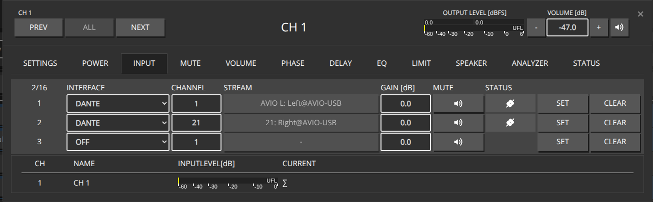
Example Configuration for CH1, CH2, CH4, CH7, switch between Dante Input 1-4 and Dante Input 21-24
HTTP Put a full json object containing all affected Channels into the http://${IP}/rest-api/settings/channel/ path
Advantage: Using the bulk endpoint /settings/channel/ allows you to patch multiple channels in a single HTTP call, which is more efficient than making individual calls for each channel. This reduces network overhead and ensures all channels are updated atomically.
To determine the source_id of the desired Interfaces, perform an HTTP OPTION call to http://${IP}/rest-api/settings/channel/1/dsp/patch' to get a list of available interfaces.
Alternatively, you can patch each channel individually by making separate HTTP PUT calls to each channel’s endpoint: http://${IP}/rest-api/settings/channel/{channel_id}/
This approach allows you to update channels one at a time, which can be useful when you need to patch channels conditionally or handle errors per channel.
Assuming we’ve already patched our desired Inputs for each channel on Slot 1 and 2
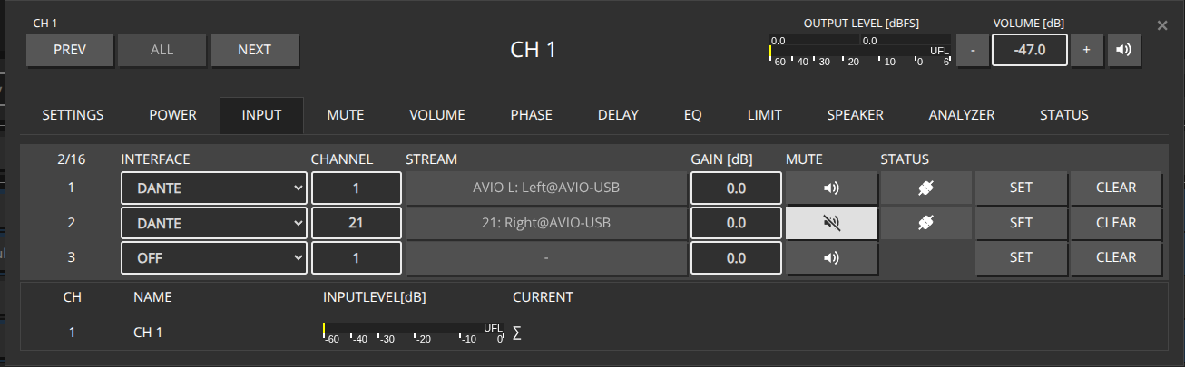
When inputs are already patched, you can toggle the mute state between different patch slots (e.g., Slot 1 and Slot 2) by only updating the mute flag in the patch object. This is more efficient than repatching the entire input configuration.
HTTP Put a JSON object containing all affected Channels into the http://${IP}/rest-api/settings/channel/ path, specifying only the patch_id and mute flag for each patch slot.
You can also toggle mute on individual channels by making separate HTTP PUT calls to each channel’s endpoint: http://${IP}/rest-api/settings/channel/{channel_id}/
Use "value": false to disable. Multi-channel updates can go through PUT /settings/channel with ampenable on each object.
2.1.11 - Save / persist
Persist runtime REST changes with /settings/save and check save status.
Runtime changes are held until they are saved. Trigger a manual save with:
PUT /settings/save (token required; no JSON body)
curl -X PUT "http://${IP}/rest-api/settings/save"\
-H "token: f4005bf8507999192162d989d5a60823"
Check save / autosave state with GET /status/save.
Note
The device may also autosave. Integrators that change many parameters in a burst should still call /settings/save when a persistent result is required (power cycle / reboot).
2.2 - Third Party Plugins
Third-party plugins that use the Maxx Control REST API against a single amplifier.
These plugins use the device REST API to control one amplifier each. For multi-amp project control, use Maxx Remote instead.
2.2.1 - Loxone Maxx Control plugin
Install the Loxone Maxx Control plugin and MAXX-CONTROL / MAXX-STATUS templates to control one Innosonix amplifier from Loxone Config.
Loxone integrators can control one Innosonix amplifier via Maxx Control using the Loxone Library plugins and example templates. Install the add-ons into Loxone Config, point each instance at the amp IP (or hostname.local), and drive mute, volume, and status over the device REST API.
What is the Loxone Maxx Control plugin?
The Loxone Maxx Control integration is a set of .LxAddon plugins from the Loxone Library that talk to a single amplifier’s Maxx Control REST API. Instantiate a plugin once per physical device.
Which Loxone templates do I need?
Because Loxone can only combine either Virtual Inputs or Virtual Outputs in a template file, two different templates have to be installed:
MAXX-CONTROL which allows to set parameters to the amplifier
MAXX-STATUS fetches Data from the Amplifier, mainly intended for Channel and Device Status
It’s totally valid to use only one, depending on your needs.
Installation
Download the corresponding .LxAddon Files and install it into your Loxone Config by double clicking or via the Import wizard like:
General
Both Plugins can be instantiated multiple times, as often as you want to control physical devices.
Note
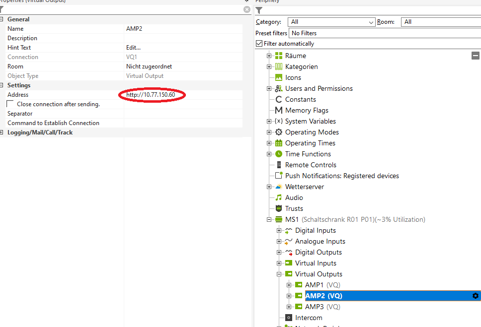
Please change the IP address for each device to its static IP or hostname.local. Leading http:// must be prepended, e.g. http://amp1.local or http://10.77.178.20.
Note
For MAXX-STATUS a trailing /rest-api/status is required as well, like http://10.77.150.60/rest-api/status
MAXX-CONTROL
Download the MAXX-CONTROL.Loxone example file from the Loxone Library
The Template basically provides the following predefined controls:
Channel Power
Channel Mute
Channel Volume
Device Identify
Device Master Mute
Device Master Volume
and some examples of how to create custom commands for improved performance.
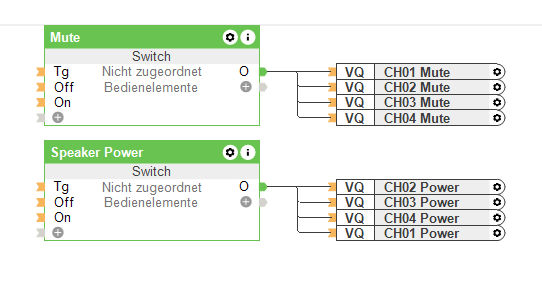
Power / Mute
Simple digital outputs which can be grouped together in any desired combination.
Note
Since each state change will send out a single HTTP request, this might cause a slight delay when a lot of channels are changed simultaneously. So, this kind of control is only recommended for a few channels. See Combined Commands to improve performance
Volume
Similar to Power / Mute Volume will send out any changes for each output as a single http request.
The interesting part here is how to map the common Loxone Analog Values in a range of 0-10 to a dB value for the amplifiers. That can be easily done with the Correction field of each output. The default configuration will map the values of 0-10 to -72dB - +10dB
This will give you almost the full dynamic range of the volume value:
Note
It’s probably more useful to restrict the volume range accessible by the user to the desired listening levels like 0-10** to -20dB - -10dB or any other suitable range for your application
Combined Commands
A basic understanding of the REST-API interface is recommended to create those combined commands.
As a starting point, have a look at the three included examples:
Multichannel Mute
Multichannel Power
Multichannel Volume
Those commands send the same value to multiple channels within a single HTTP request, significantly improving performance when many channels are involved in a call.
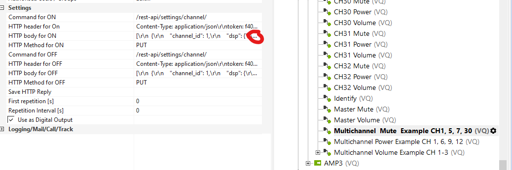
Multichannel Mute
Let’s have a look at the HTTP body which is sent out when the DIGITAL OUTPUT is set to ON by clicking on the edit button of that line:
You basically see a JSON payload file containing an ARRAY of single JSON objects for the corresponding channels, indicated by the channel_id tag:
for each channel, you want to control and change the channel_id to the desired channel number.
Note
Don’t forget the trailing comma "," after each object, except the last one! Please use any JSON validator to verify the final JSON object before putting it back into Loxone Config
Note
Copy and paste the JSON payload to any text editor and replace the "value": true with "value": false and insert that object into the HTTP body for OFF
MAXX-STATUS
Download the MAXX-STATUS.Loxone example file from the Loxone Library
The MAXX-STATUS Template periodically polls the /rest-api/status URL of the amplifier and filters the response for each channel status/device status.
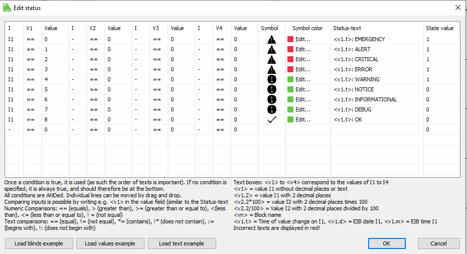
The raw CHxx STATUS value represents the default syslog severity levels like:
STATUS
Level
0
EMERGENCY
1
ALERT
2
CRITICAL
3
ERROR
4
WARNING
5
NOTICE
6
INFORMATIONAL
7
DEBUG
8
OK
In combination with the provided STATUS component with the following settings:
An easy virtualization can be achieved.
Combining the Val output of each STATUS component with an OR Gate, a simple GLOBAL STATUS can be generated when any channels or device assert any state higher than NOTICE ( see STATUS settings, State value).
2.2.2 - Q-SYS Maxx Control plugin
Install the Q-SYS Maxx Control plugin in Q-SYS Designer 9.8+ to control mute, volume, status, and more on one Innosonix amplifier.
Q-SYS integrators can control one Innosonix amplifier via Maxx Control using the Innosonix Maxx Control plug-in for Q-SYS Designer. Add the plug-in to your design, enter the amp IP, and expose mute, volume, meters, and status to Q-SYS UCIs and logic.
What is the Q-SYS Maxx Control plugin?
Innosonix provides a plug-in that integrates Maxx Series amplifiers (Maxx Control) with the QSC Q-SYS ecosystem. Devices can then be controlled from Q-SYS Designer, Q-SYS compatible user-control interfaces, and GPIO logic on Q-SYS cores and peripherals.
Innosonix devices must have firmware version V3.19.4 or above installed to be compatible with the Maxx Control Plug-in. If you are unsure what firmware you device is currently using, please download IDFM to help confirm and if need be install up to date firmware.
For further control and processing capabilties of your Maxx Device please download Maxx Remote
How do I install it in Q-SYS Designer?
Download the Innosonix Maxx Control Plug-in from the Third Party Downloads section of the Downloads section of our website.
Copy the downloaded plug-in file into the My Documents/QSC/Q-Sys Designer/Plugins folder (exact filename is in the download package from the Innosonix website).
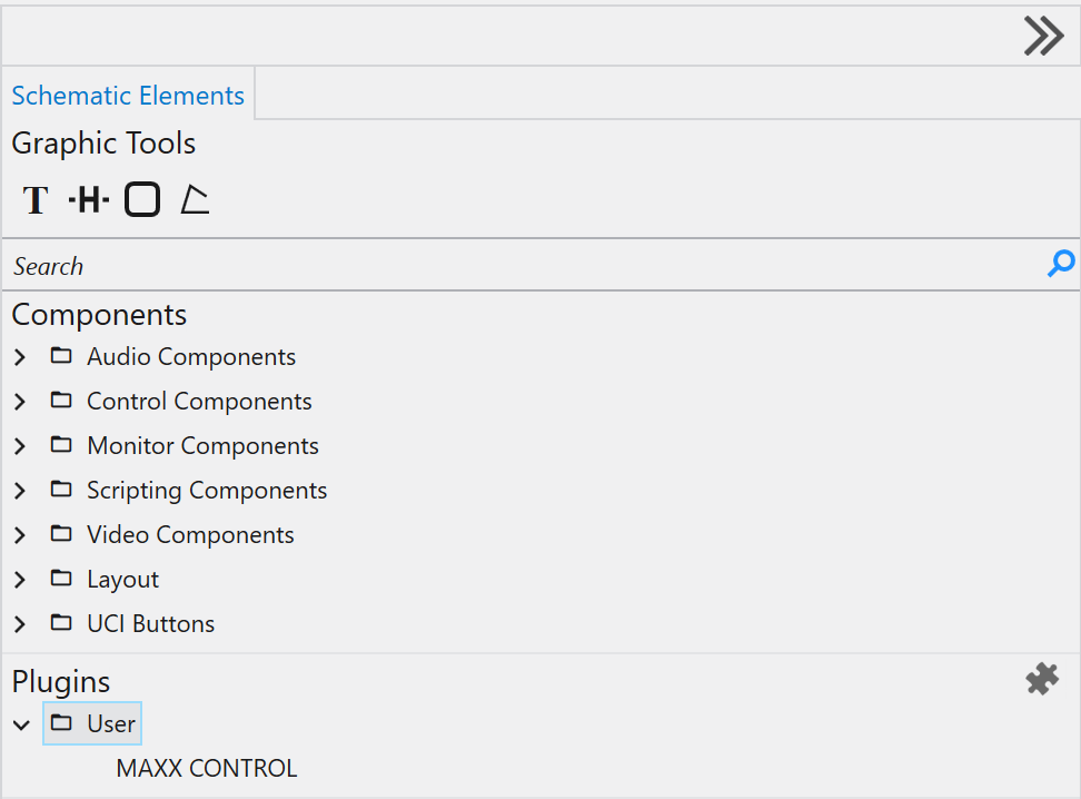
Open Q-SYS Designer; the plug-in appears under Schematic Elements → Plugins:
Drag and drop the Plug-in into your design and select it by clicking once on the Plug-in icon.
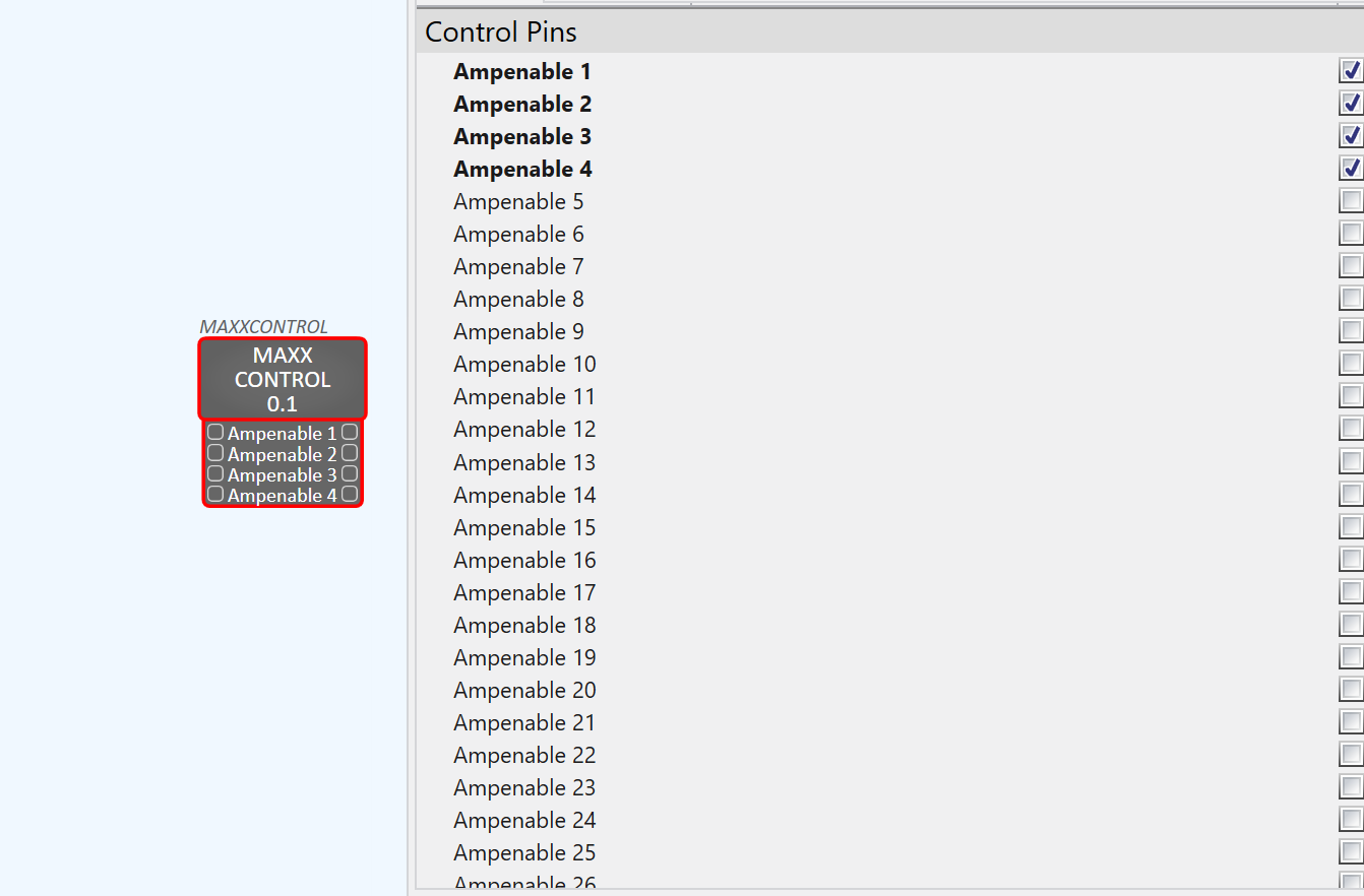
Control pins can be enabled by ticking the check-boxes in the “Control Pins” section as required:
Go “Online” with your Q-Sys project. If devices are not connected you can use the “Emulate” function under the “File” tab in the menu above.
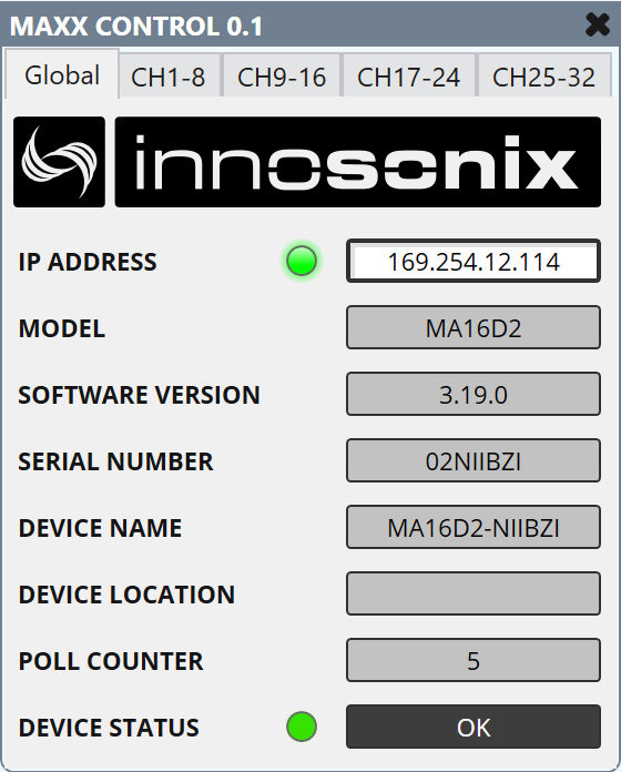
Double-click the plug-in icon, open the Global tab, and enter the amplifier IP address. The IP is shown on the device front panel, or use IDFM to discover it:
The “Global Tab” notifies the user of important information on the Innosonix device including:
IP Address
Model
Software Version
Serial Number
Device Name
Device Location
Pole Counter
Device Status
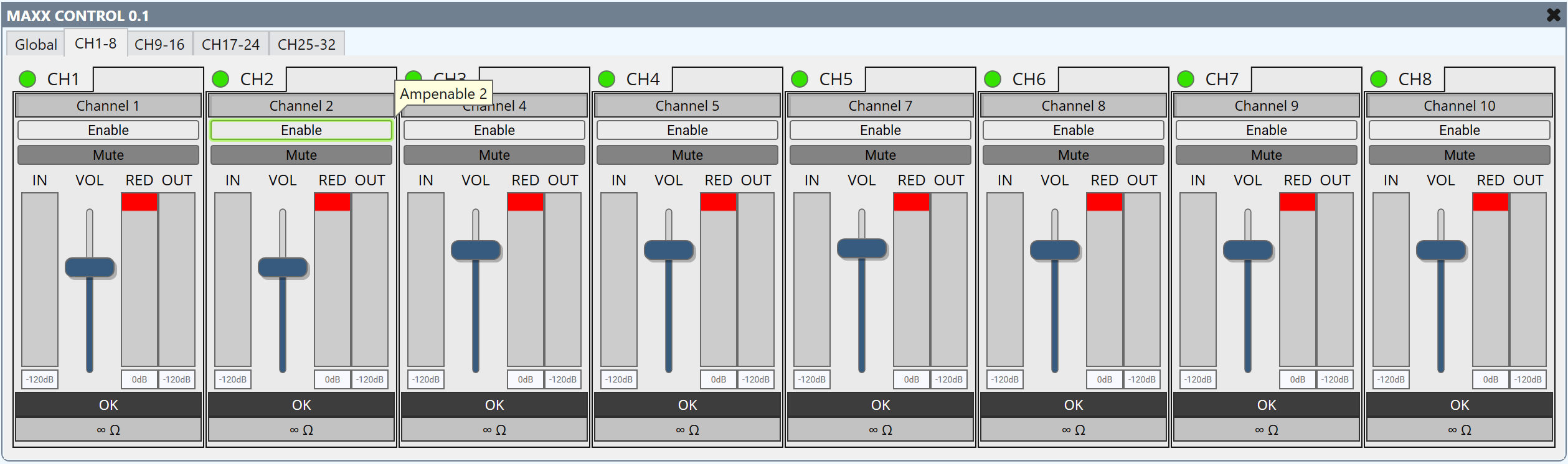
Select the “Channels Tab”:
Within the “Channels Tab” the user has the facility to adjust a number of the devices features including:
Mute
Enable or Disable Channel
Volume
Further Assistance:
For any more information please visit feel free to Contact us!
3 - Maxx Remote
Maxx Remote is Innosonix project-based control for multiple amplifiers: design channels and groups, tune offline, then link to real outputs including micro MAXX.
Maxx Remote is the project-based control software for Innosonix amplifiers. You design the system as channels (speakers) and groups (rooms or zones), then link those to real amplifier outputs when the hardware is available. micro MAXX amplifiers have full Maxx Remote support alongside other MAXX models.
What / when / how: use Maxx Remote when one site has many amplifiers or you need room-level groups, offline projects, or undo/redo while tuning. Install the Desktop app or Docker server, create a project, add channels and groups, link devices, then operate from GROUPS / CHANNELS / VIEW.
Use Maxx Remote when you need:
One place to tune and operate many amplifiers
Groups for room-level volume, mute, EQ, and routing
Offline planning before the amps are on site
Undo / redo while dialing in a system
Operator-friendly VIEW pages for day-to-day control
Desktop vs Server
Form
Best for
How you open it
Desktop application
Design, commissioning, laptop use on site
Portable app (Windows / macOS / Linux) from the downloads page
Server (Docker)
Always-on control in a rack or server room
Docker image; open http://<host>:8000 in a browser
Both forms run the same Maxx Remote server and web UI. The Desktop app includes the server; Docker exposes the same UI on port 8000.
Once a device is linked and controlled from Maxx Remote, treat Maxx Remote as the source of truth. Changing the same channels in Maxx Control can create an Out of Sync state.
GUI reference and API when you need screen-level or integration detail
3.1 - Concept
How Maxx Remote thinks about channels, groups, devices, and output levels.
Goal / when to use
Read this once before you build a project. Maxx Remote sits between your speakers / rooms and the amplifier hardware, so you can tune and operate without constantly asking “which amp, which output?”
Mental model
Maxx Remote is an abstraction layer over amplifier outputs. It does not matter whether 1,000 speakers sit on thirty-two 32-channel amplifiers or on many smaller units — you work with project channels and groups.
As an operator or tuner, you usually care about this speaker or this room, not which physical output is used that day. Linking can change later; the channel settings stay in the project.
System overview
Desktop / Server and UI
Maxx Remote always consists of:
A server that holds the project and talks to amplifiers
A web UI (the screens you use in the browser or Desktop window)
Access the UI at http://localhost:8000 on the machine running the server (or http://<server-ip>:8000 for Docker / remote hosts).
Objects you will use
Object
What it means in the room
Channel (project channel)
One speaker (or speaker strip) with full DSP: volume, EQ, delay, mute, and more
Group
A room or zone that can adjust the same kinds of parameters for many channels at once
Device
An amplifier in the project (for example 8 / 16 / 24 / 32 outputs, depending on model)
HW channel
A physical amplifier output, for example CH1 on AMP1
How they relate
A channel behaves like a channel strip: you can set it directly.
If that channel also belongs to one or more groups, group values are added (summed) with the channel’s own values. The result is what the amplifier should play.
Example for volume:
Source
Volume
Channel
−2 dB
Group 1
−1 dB
Group 2
+5 dB
Output
+2 dB
When a channel is linked to a HW channel, Maxx Remote sends that output result to the device.
Because settings live in the Maxx Remote project, you can replace an amplifier or re-link speakers to different outputs without rebuilding the whole tuning from scratch.
Out of Sync
After a channel is linked, Maxx Remote periodically compares project data with the device. Someone can still change the amp from Maxx Control or other tools — Maxx Remote then reports OUT OF SYNC for the mismatched parameters.
Important
Do not use Maxx Control for day-to-day control of devices that Maxx Remote already owns. Data direction is Maxx Remote → device.
You resolve sync by aligning values in Maxx Remote with the device, or by pushing project data to the device (SYNC). Details: Troubleshoot.
Expected result
You understand that:
Channels and groups are how you design and operate the system
Devices and HW channels are how sound reaches the speakers
Output levels are the sum of channel + group contributions
Common mistakes
Common mistakes
Tuning only on the device UI while Maxx Remote is connected — this causes Out of Sync.
Expecting the CHANNELS list to show “group-only” values — CHANNELS shows the final output.
Thinking a channel can live on only one group — a channel can belong to multiple groups.
Install Maxx Remote as a portable Desktop app or run it as a Docker server.
Goal / when to use
Get Maxx Remote running so you can open the UI and create or load a project.
Choose Desktop for commissioning laptops and day-to-day design work.
Choose Docker for an always-on server that browsers can reach on the network.
Prerequisites
Supported OS for Desktop, or a host that can run Docker
Network access to your amplifiers (see Prerequisites)
For automatic discovery (amplifiers and Dante TX sources): the host must receive the UDP broadcast / multicast traffic listed under Ports and discovery — on Docker that means host networking
Unpack or place the portable application where you want it — no installer is required.
Start the application.
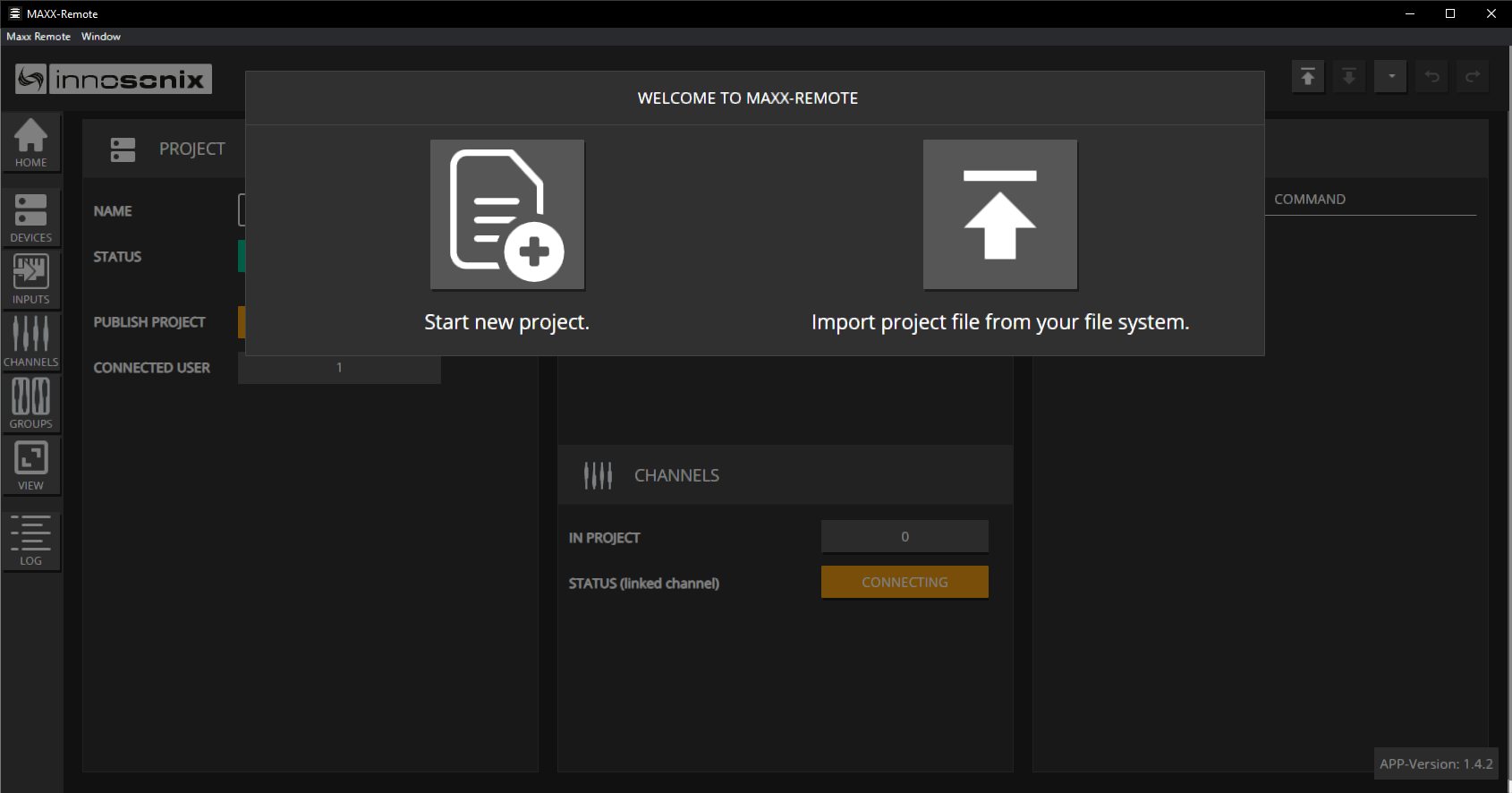
On first launch, use Start a new project or import an existing project archive.
Expected result
The Maxx Remote window opens with the project splash / HOME UI. You can also reach the same UI in a browser at http://localhost:8000 while the Desktop app is running.
Server / Docker
Ports and discovery
Maxx Remote listens for more than the web UI. Automatic discovery uses UDP broadcast and multicast, which Docker’s default bridge network does not forward reliably when you only publish ports with -p.
Maxx Remote also sends outbound unicast UDP to Dante devices (ARC channel queries, typically ports 4440 / 4444 / 4455, and CMC registration, typically 8800). Those are device-side ports — they are not something you “publish” on the container; the host firewall must allow the outbound path.
Why host networking?
Publishing individual UDP ports with -p maps unicast traffic into the container. Discovery needs broadcast (amplifiers) and multicast with IGMP joins (Dante / mDNS). On a Docker bridge those packets usually never reach the process — so ADD FROM NETWORK and Dante TX discovery stay empty even if you map every port above.
Recommended: host network (discovery works)
Use host networking whenever you want automatic amplifier scan or Dante TX discovery:
docker run --detach --name maxx-remote --network host innosonix/maxx-remote:latest
Once the container is running, open:
http://<docker-host-ip>:8000
Note
--network host is the approach used by Innosonix’s own deploy scripts. It is the simplest reliable way to put the process on the same L2 segment as amplifiers and Dante devices.
Alternative: published ports (UI only — no discovery)
If you only need the web UI and will add amplifiers by IP / hostname (and do not rely on Maxx Remote’s Dante discovery), bridge networking with a published HTTP port is fine:
services:maxx-remote:image:innosonix/maxx-remote:latestports:- "8000:8000"# Discovery (INX + Dante) will not work reliably on the default bridge.# Prefer network_mode: host when you need ADD FROM NETWORK or Dante TX scan.
Do not expect a long -p 9453:9453/udp -p 5353:5353/udp … list to replace --network host for discovery. Map TCP 8000 for the UI; use host networking when discovery matters.
Persist project data (recommended)
Warning
If you start the container without a volume, the project lives only inside the container. Deleting or recreating the container deletes that data.
Option A — Export / import yourself
Use the UI Export / Import controls when you migrate to a new container.
Browsers on the network can open the Maxx Remote UI on port 8000, and projects survive container restarts when a volume is mounted. With --network host, ADD FROM NETWORK and Dante TX discovery can see devices on the same LAN segment.
Common mistakes
Common mistakes
Running Docker without--network host and wondering why ADD FROM NETWORK or Dante sources stay empty — discovery needs UDP broadcast 9453 plus Dante/mDNS multicast, not only published ports.
Assuming -p 9453:9453/udp (or similar) is enough — bridge networking still breaks broadcast/multicast for discovery.
Recreating a container without a volume or export — project gone.
Confusing port 8000 (UI / API) with discovery traffic (9453, 5353, 8702, 8708).
Always start network and firmware setup in IDFM. Maxx Remote assumes devices are already reachable.
2. Ports and reachability
Traffic
Address / port
Purpose
TCP 8000
host :8000
Maxx Remote UI and REST API (http://host:8000, OpenAPI at /api-docs/)
UDP 9453
broadcast 255.255.255.255
Innosonix amplifier discovery (INX / IDFM)
UDP 5353
multicast 224.0.0.251
mDNS used for Dante device discovery
UDP 8702
multicast 224.0.0.231
Dante control-plane notifications
UDP 8708
multicast 224.0.0.233
Dante heartbeats
Outbound (device-side ports Maxx Remote talks to, not listens on): Dante ARC queries typically 4440 / 4444 / 4455, CMC registration typically 8800.
Firewall / VLAN notes:
The PC or Docker host must reach each amplifier’s management IP (HTTP/API used by Maxx Remote).
Discovery broadcast/multicast usually do not cross routers. Across subnets, add amplifiers by hostname + IP instead of relying on scan.
Docker: use --network host for automatic INX and Dante discovery. Publishing only -p 8000:8000 is enough for the UI if you add devices manually — see Installation.
3. Dante (audio network)
If you use Dante input sources:
Amplifiers and sources must share a working Dante network (often separate from or VLAN’d from control).
Maxx Remote discovers Dante TX channels on the LAN (mDNS + multicast control plane above). You can still use Dante Controller (or equivalent) to confirm Transmit Channel@Hostname names when creating INPUTS.
Maxx Remote can create dynamic Dante subscriptions (often shown with a D: prefix in Dante Controller).
On Docker, Dante discovery needs the same host-network path as amplifier discovery — bridge -p mappings are not enough.
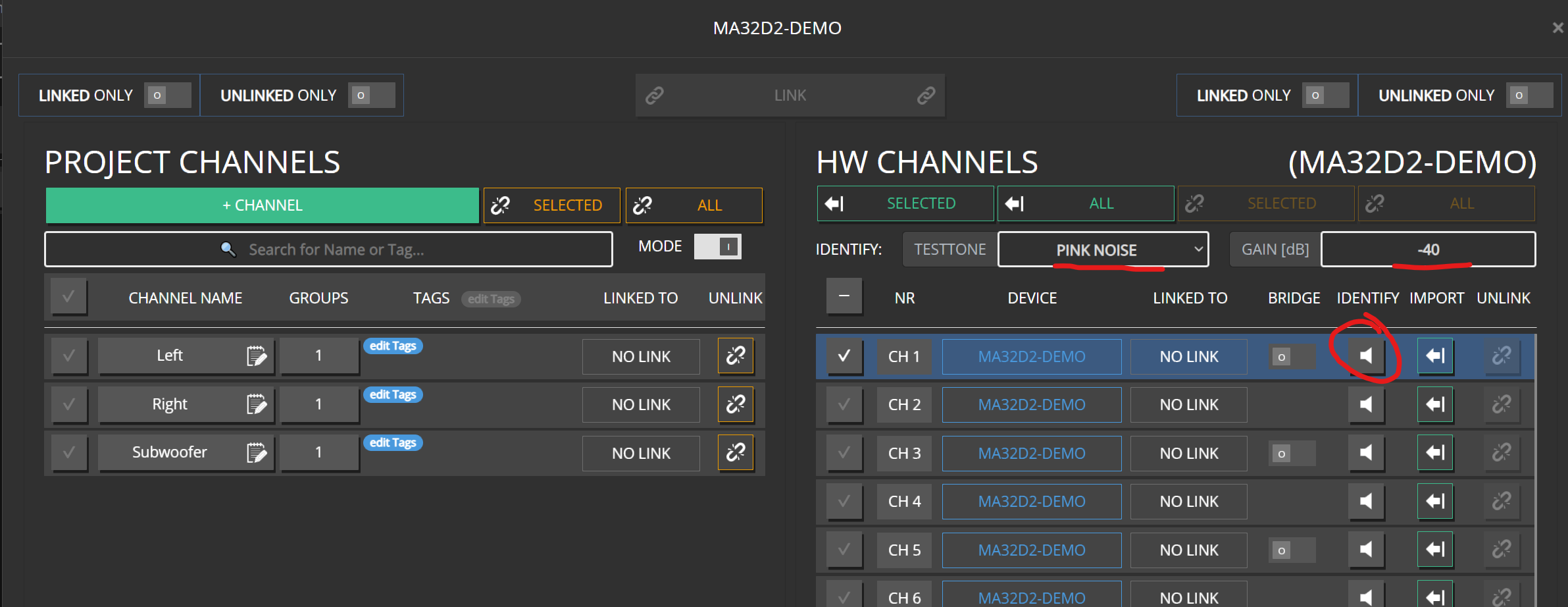
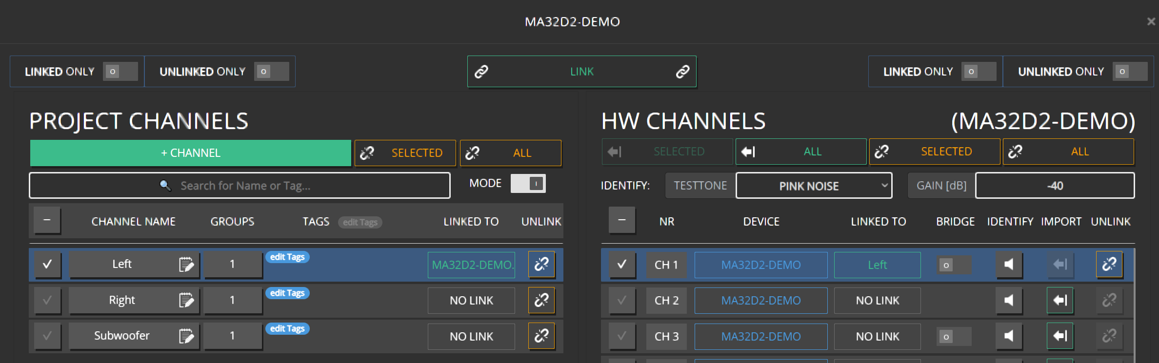
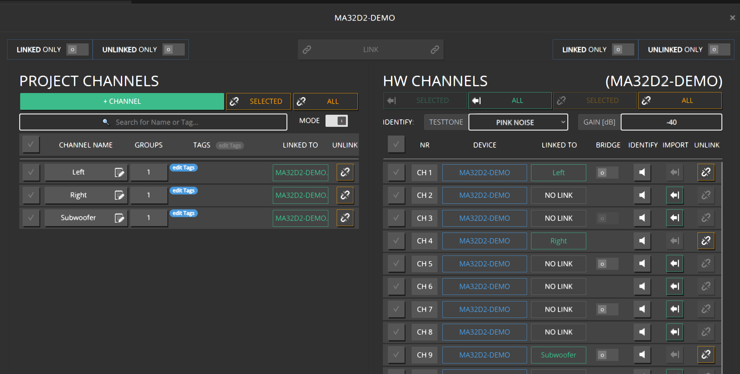
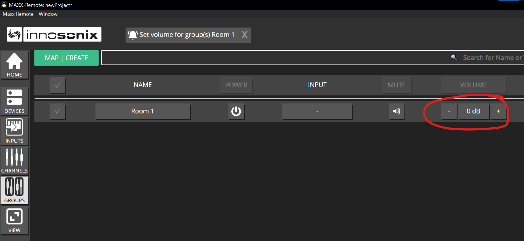
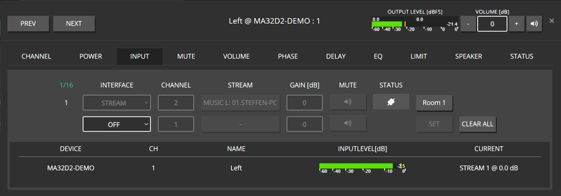
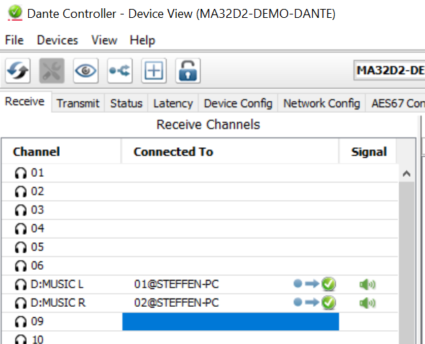
Guided demo: Left / Right / Sub on an MA32/D² with Dante music.
Goal / when to use
Get first music out of a simple system: three speakers (Left, Right, Sub) on an MA32/D², with group volume/EQ and a stereo Dante source (for example Dante Virtual Soundcard).
Create, open, save, export, and persist Maxx Remote projects — including offline planning and Docker volumes.
Goal / when to use
Manage the project file that holds your channels, groups, devices, inputs, views, and tuning. Use this when starting a job, moving between machines, or keeping a Docker server’s configuration safe.
Prerequisites
Maxx Remote Desktop or Server running (Installation)
Create a new project
Desktop or browser splash
Start Maxx Remote with no project loaded.
Choose Start a new project.
Enter a clear site name (for example Museum-Floor2).
Desktop menu (Electron)
Use the application menu when available:
New Project
Load Project / Last Projects
Save Project / Save Project As
Close Project
Expected result
HOME shows the new project name; DEVICE / CHANNEL counts start empty.
Open / import an existing project
On the splash screen, choose Import project archive to host, or
Use the top-bar Import control to upload a project archive or partial JSON.
Expected result
HOME and list pages populate with the imported project.
Export / backup
Use the top-bar Export control.
Store the download with your site documentation.
Export before:
Updating Maxx Remote
Recreating a Docker container
Handing the project to another engineer
Offline planning
You can design without amplifiers:
Create channels and groups.
Set volumes, EQ, delay, mute, speaker presets.
Define INPUTS and roles (even if Dante is not online yet).
Optional: sketch which speakers belong to which rooms
Create channels
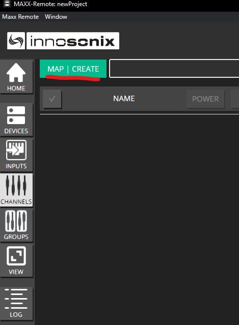
Open CHANNELS → MAP | CREATE.
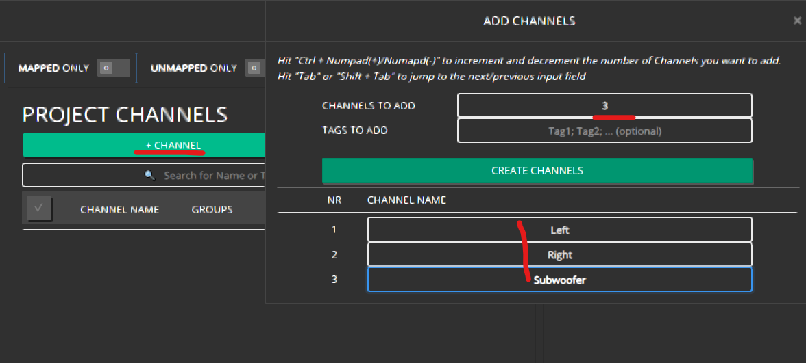
Click + CHANNEL.
Set how many channels to add and name them (for example Lobby Left, Lobby Right).
Click CREATE CHANNELS.
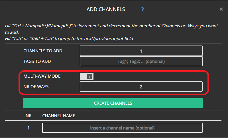
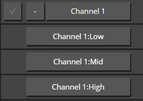
For multi-way cabinets (one channel object with Low/Mid/High ways), enable MULTI-WAY MODE — see Multi-way channels.
Expected result
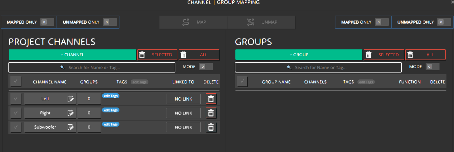
Channels appear in the CHANNELS list with empty LINKED TO until devices are linked.
Create groups
In MAP | CREATE, click + GROUP.
Name the group after the room or zone (for example Foyer, Hall A).
Create the group.
Expected result
The group appears in GROUPS and in the mapping lists.
Map channels into groups
Stay in CHANNEL | GROUP MAPPING (MAP | CREATE).
Select one or more channels.
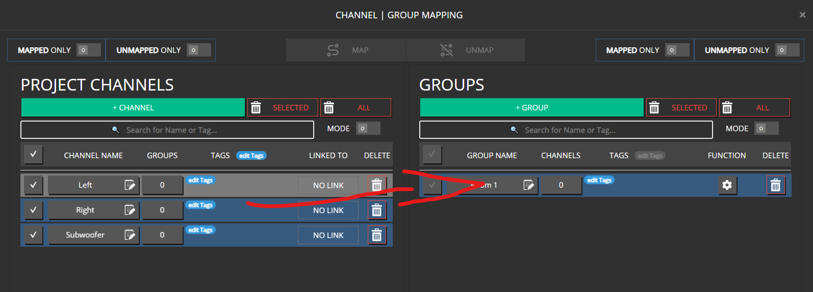
Drag them onto a group, or click MAP.
Use UNMAP when a speaker should leave a room.
Filters MAPPED ONLY / UNMAPPED ONLY help large projects.
Hint
One channel may belong to several groups (for example room group + “All Subs” group). Remember that group values sum with the channel (Concept).
Expected result
Groups show their member channels; CHANNELS can show group membership.
Choose what a group can control
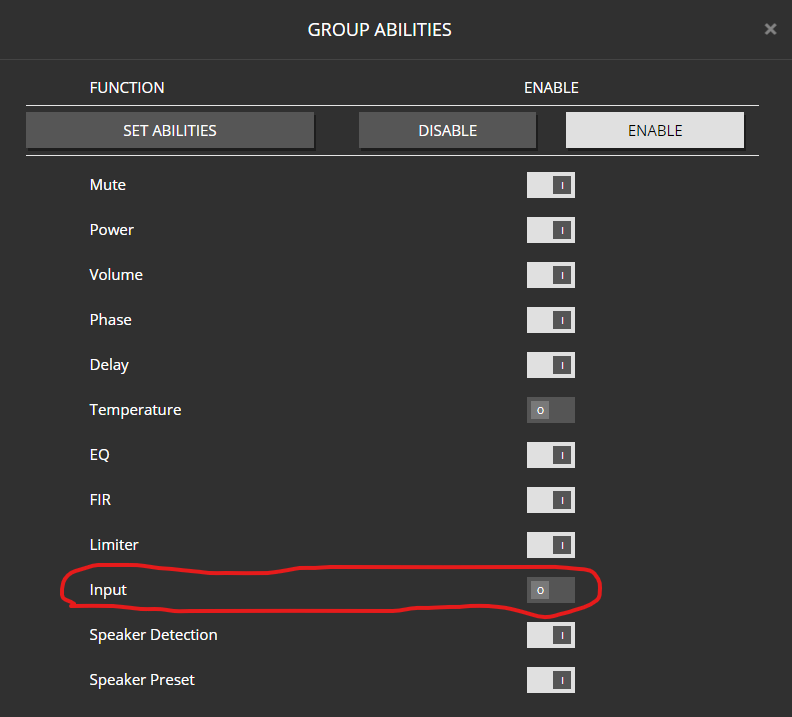
On a group’s edit dialog, GROUP ABILITIES decide which controls the group exposes (Mute, Volume, EQ, Input, Speaker Preset, and more). Turn off abilities you do not want operators to touch at group level.
Expected result
GROUPS overview and edit tabs match the abilities you enabled.
Channel roles (for inputs)
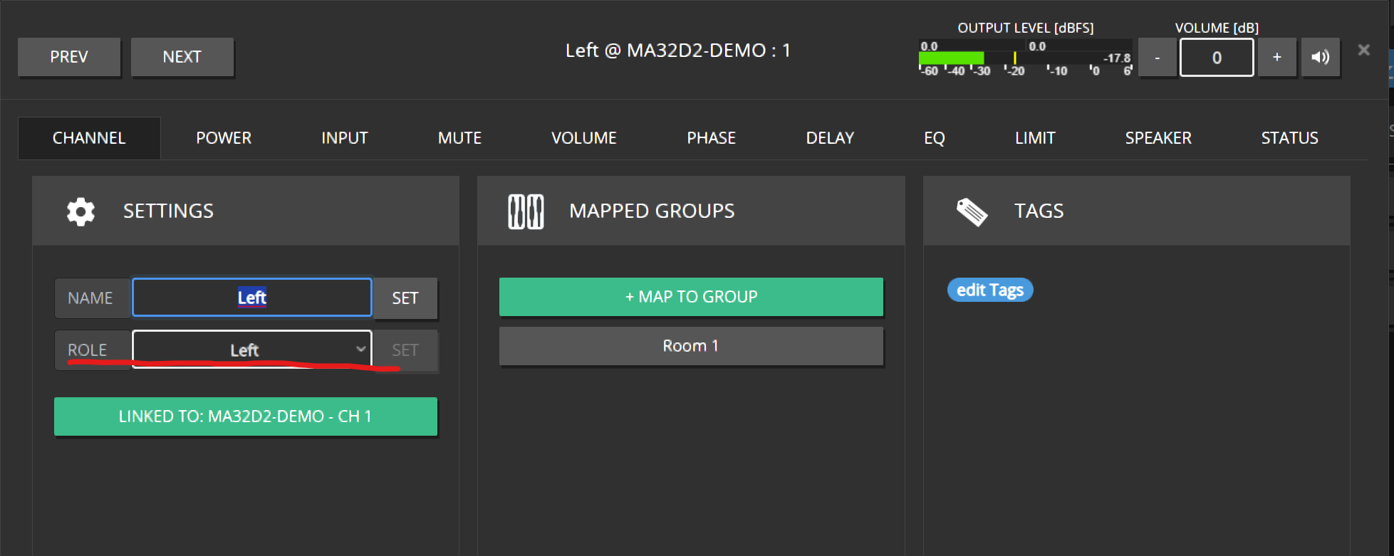
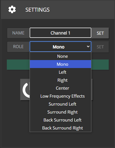
Set each channel’s ROLE (Left, Right, Mono, Center, LFE, surrounds, …) so group INPUT assignment routes the correct Dante legs. Details: Inputs and routing, Surround.
Common mistakes
Common mistakes
Creating one channel per amp output “just because,” then drowning in unused strips — create channels for speakers you care about.
Putting the same channel in two groups that both apply large EQ/volume — outputs stack.
Naming channels after amp slots (CH12) instead of room positions — harder later when you re-link.
Enter an offset relative to the current summed output workflow you are using → SET.
Note
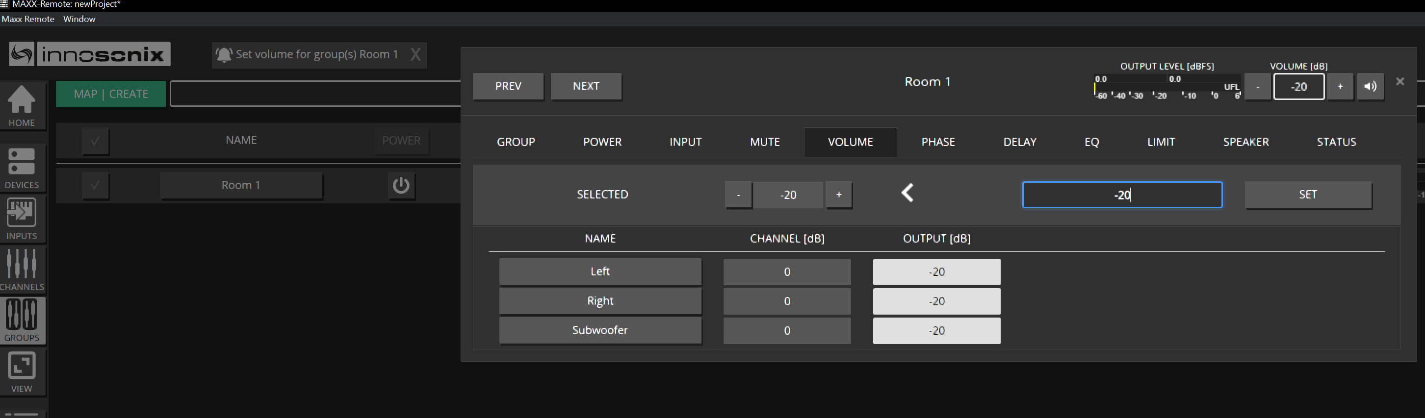
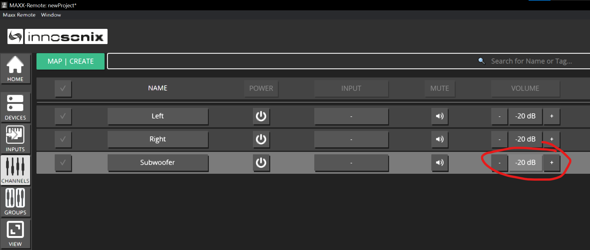
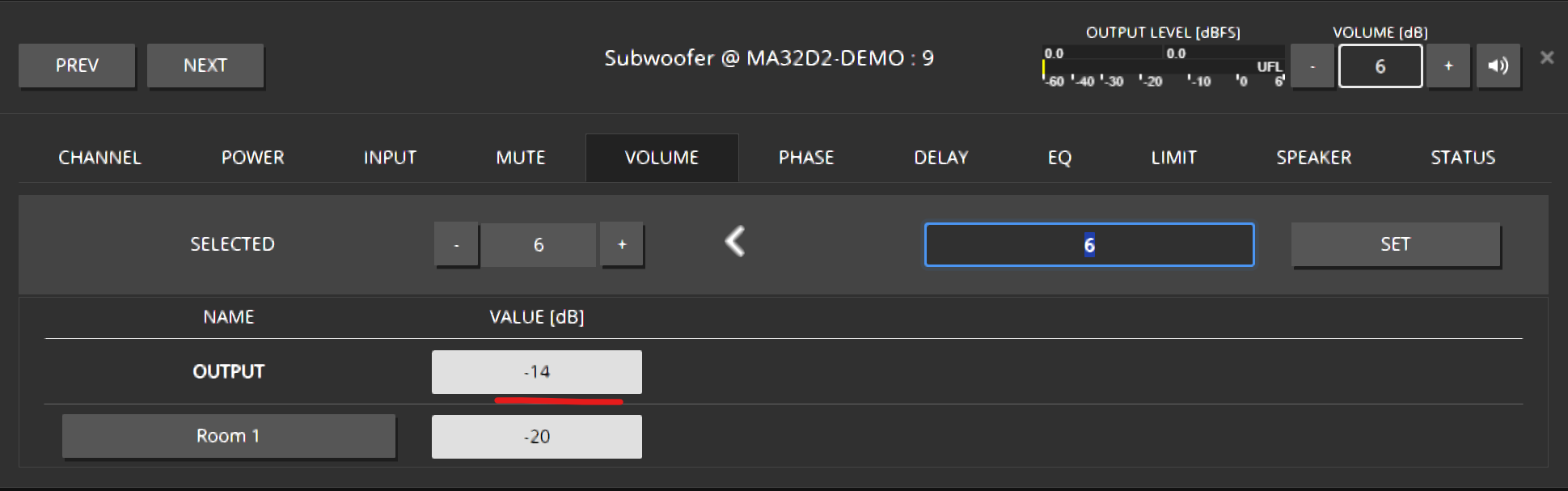
CHANNELS always shows the final output (channel + all groups). That is why a channel may already read −20 dB after a group change.
Mute and power
Use group MUTE for room silence.
Use channel MUTE for a single speaker.
POWER controls (where available) can be driven from channel, group, or operator VIEW widgets.
EQ
Open EQ from the channel or group row (EQ icon / edit dialog EQ tab).
Drag filter types (PEQ, shelves, HP/LP, …) into the plot.
Select a filter, set type (gear), frequency, gain, Q.
On a channel, review the summed curve when groups also contribute EQ.
Delay and phase
Open the channel or group edit dialog → DELAY / PHASE.
Set delay for alignment; use phase invert when polarity must flip.
Prefer group delay only when the whole room should shift together.
Limiters, FIR, speaker tools
Advanced DSP (limiters, FIR, speaker detection, speaker presets) lives in the channel / group edit tabs (LIMIT, SPEAKER, …). For packaged speaker tunings see Speaker presets.
Bulk edits
On CHANNELS / GROUPS list pages, column headers such as VOLUME, MUTE, DELAY, PHASE open editors that can apply to the current selection — useful for many identical fills.
Undo / redo
Maxx Remote supports undo/redo for project edits — use it while tuning instead of guessing previous values.
Expected result
Rooms sit at safe levels; individual speakers are trimmed; EQ/delay match the design intent; CHANNELS output values match what you hear.
Common mistakes
Common mistakes
Turning channel volume up to “fix” a group that is muted.
Building the same EQ twice (channel + group) without noticing summation.
Tuning in Maxx Control in parallel — creates Out of Sync.
Forgetting IDENTIFY before applying aggressive EQ to the wrong linked output.
Operators adjust the intended rooms without accessing CHANNELS / DEVICES commissioning screens.
Snapshots (groups)
Where available, group SNAPSHOTS store and recall sets of group-related settings for scene changes. Use them for rehearsed level/EQ scenes — not as a substitute for project export.
Expected result
Day-to-day control happens mostly from GROUPS and VIEW; CHANNELS is for trim and diagnosis; OUT OF SYNC stays clear.
Common mistakes
Common mistakes
Letting operators work in CHANNELS and stack accidental trims.
Sharing the full Maxx Remote UI instead of a VIEW link.
Represent one loudspeaker cabinet as a single channel with 2 / 3 / 4 amp ways.
Goal / when to use
Use a multi-way channel when one physical speaker cabinet needs several amplifier outputs (for example low / mid / high). You still control the cabinet as one channel, while each way holds driver-specific DSP.
Name the parent channels and click CREATE CHANNELS.
Expected result
Each new channel is a parent cabinet with fixed child ways (not separately deletable).
Convert an existing channel
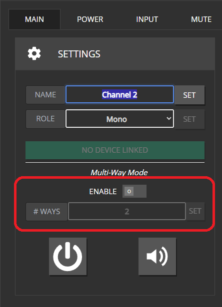
Open the channel edit dialog → MAIN.
Enable multi-way (or change way count) and confirm the popup.
You can pre-set the way count before enabling.
You cannot change multi-way configuration while the channel is linked to a device. Unlink first.
Note
Ways are always tied to their parent. They disappear only when you delete the parent, disable multi-way, or reduce the way count.
Naming
Ways are named from the parent plus a role:
Ways
Roles
2
Low, High
3
Low, Mid, High
4
Sub, Low, Mid, High
Link multi-way channels
Linking is like normal channels, with a few extras:
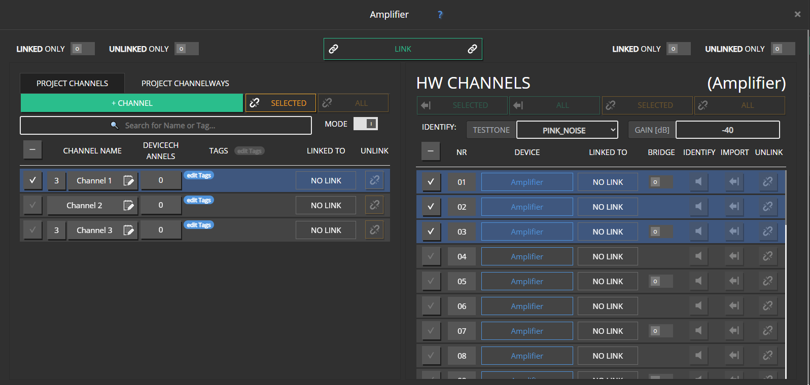
Open DEVICES → LINK CHs.
Multi-way parents show their way count.
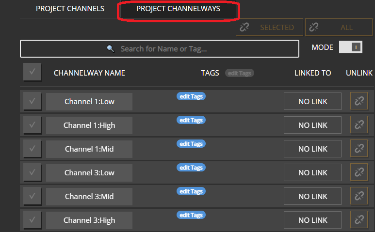
Use the PROJECT CHANNELWAYS tab to link individual ways (different amps or non-default order).
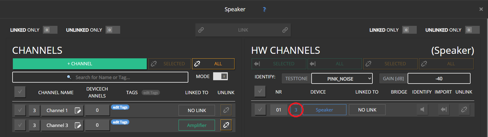
On the PROJECT CHANNELS tab, select the matching number of device channels before LINK unlocks (3-way → 3 HW channels).
Drag and drop rules
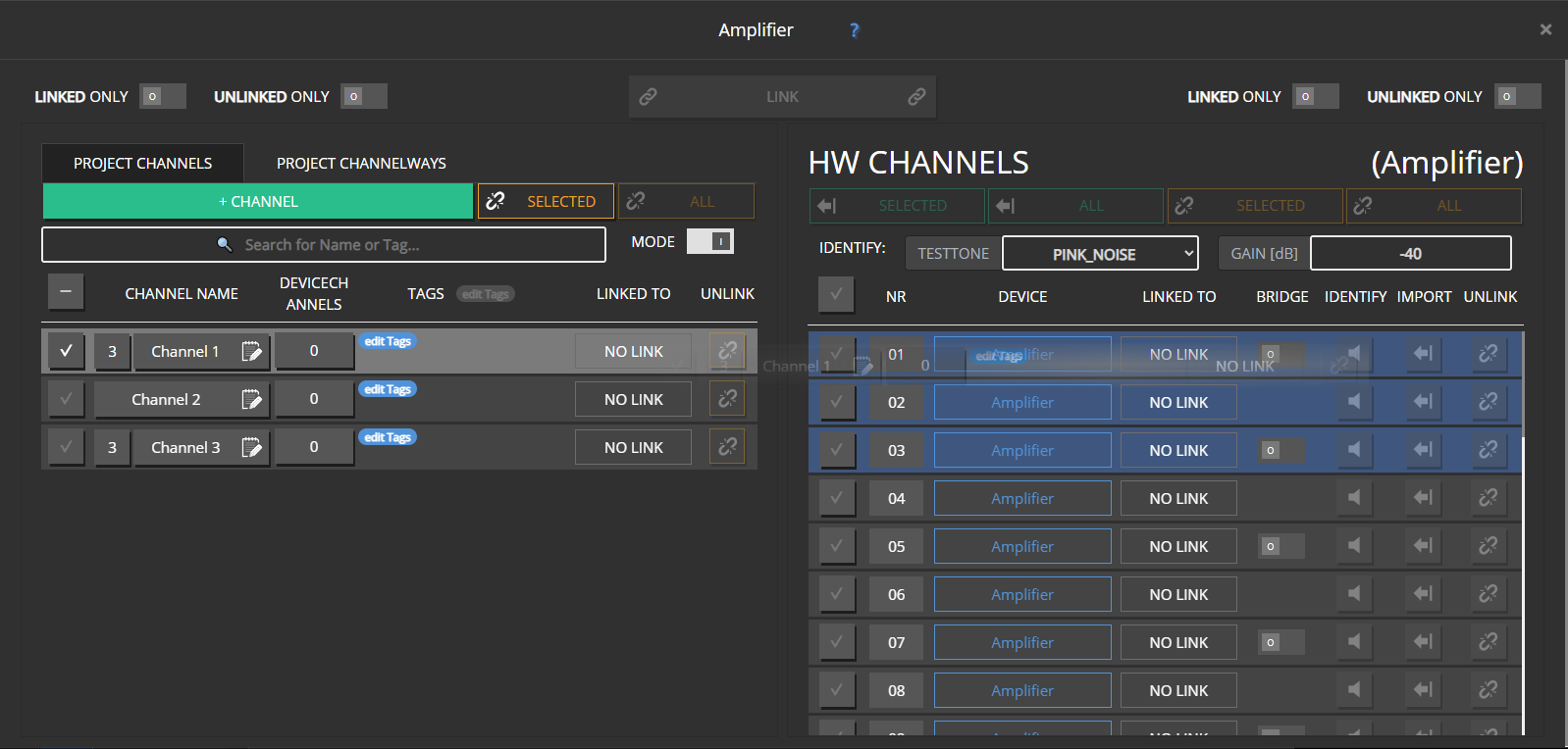
Dragging a multi-way parent highlights the matching number of HW channels.
Dragging HW channels onto a parent requires the same count.
Extra HW channels continue to the next project channel in line.
Whole-cabinet links assign HW channels low → high in list order.
Changing way count on an already linked channel is blocked on purpose — it would leave orphan ways or outputs. Unlink, reconfigure, then link again. Use the CHANNELWAYS tab when ways must land on different devices.
Speaker-style devices
Some amplifiers present as a single “speaker” device with a fixed internal way layout. For those:
Link a matching multi-way parent as a whole — not individual ways.
The linker filters to parents with the correct way count (shown next to the device name).
How settings combine
Parent settings and way settings combine much like group + channel. For limited DSP resources (EQ, FIR, limiters, speaker detection), a way’s own settings take precedence when the hardware cannot hold everything. Parent values may already include group contributions.
UI differences
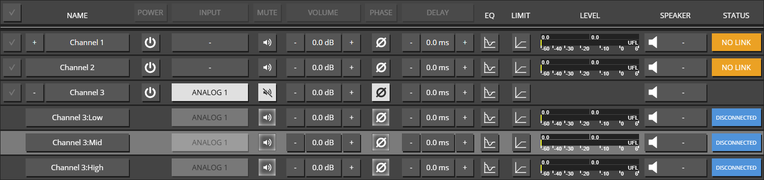
CHANNELS overview
Ways are not multi-selected for bulk edits — edit the parent for “whole cabinet” changes.
Ways have no separate power control; INPUT on ways is read-only (inherited).
Parent level meter shows the combined level of its ways; STATUS combines way status.
Edit dialogs
Way editor: no Power / Input tabs; name read-only; no channel role / multi-way section.
Parent SPEAKER tab: no one-shot speaker detection (set per way).
Parent STATUS lists way status (similar to groups listing members).
Common mistakes
Common mistakes
Trying to rename or delete a single way — only the parent is editable that way.
Linking three HW channels out of order without using the CHANNELWAYS tab.
Applying a 2-way speaker preset to a 3-way parent (Speaker presets).
5.1 / 7.1 roles, group output setups, and crossmix strategies in Maxx Remote.
Goal / when to use
Route surround program (5.1 / 7.1 and related) into rooms when the speaker layout and the source layout are not always identical. For basic stereo INPUTS, start with Inputs and routing or Quick-Start.
Prerequisites
Groups with Input ability enabled
Channels created and given surround ROLEs
Dante TX labels known for every surround leg
Surround channel names in Maxx Remote
Naming varies across the industry. Maxx Remote uses:
5.1
Center (C)
Left (L)
Right (R)
Left Surround (Ls)
Right Surround (Rs)
Low Frequency Effect (LFE)
7.1
Center (C)
Left (L)
Right (R)
Left Surround (Ls)
Right Surround (Rs)
Back Surround Left (Bsl)
Back Surround Right (Bsr)
Low Frequency Effect (LFE)
Note
LFE speaker position is not fixed in every room — place it as your design requires.
Create surround INPUT SOURCES
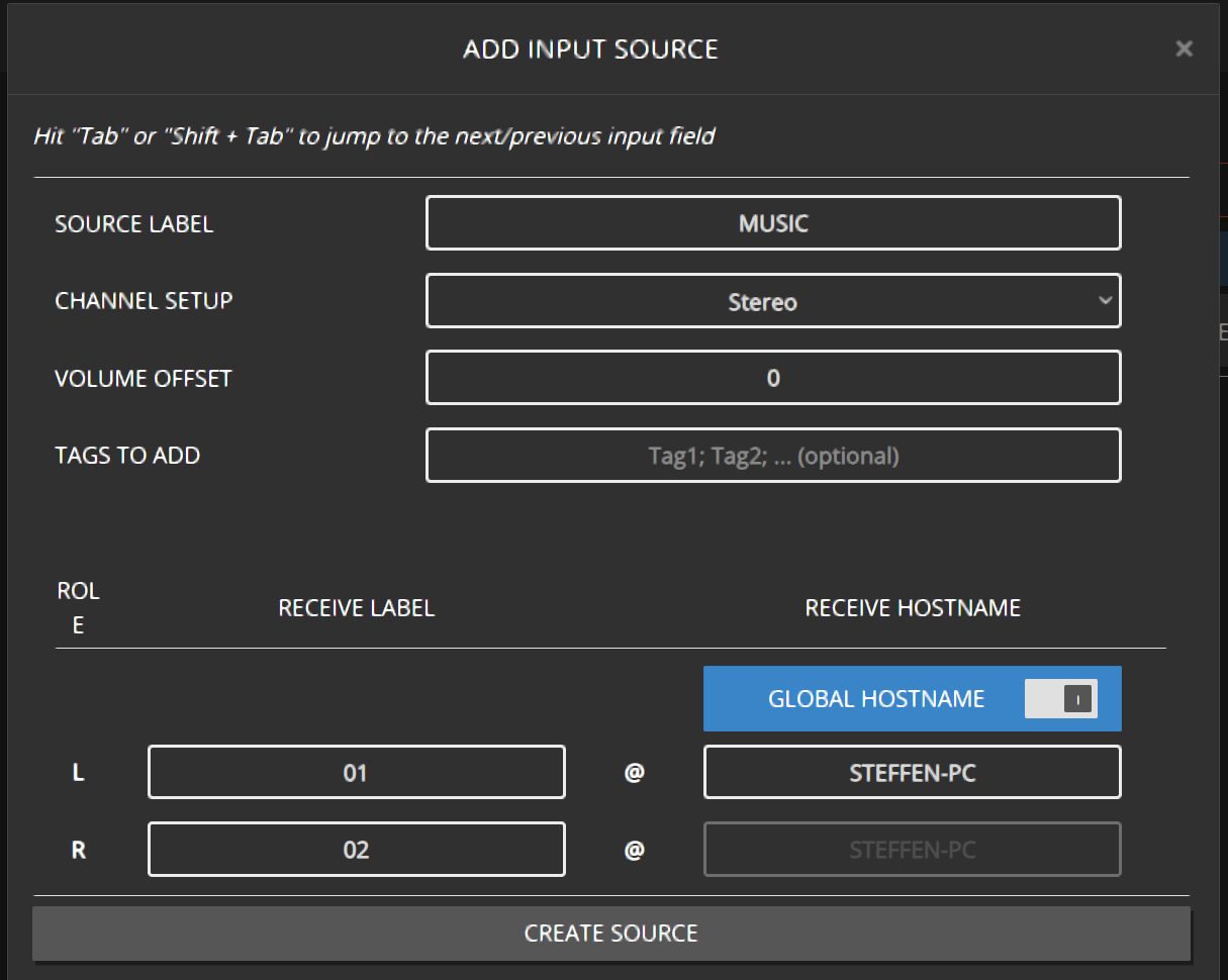
Same workflow as stereo INPUTS, with more RECEIVE LABEL entries — one per surround leg. See Quick-Start · inputs.
Channel roles
Assign each speaker channel a role. NONE receives no INPUT SOURCE streams. MONO usually receives a combination of legs (see crossmix).
Group output / channel setup
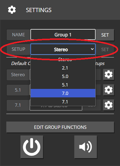
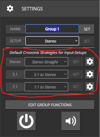
On GROUPS, set output / channel setup to match the room (Stereo, 2.1, 5.0, 5.1, 7.0, 7.1, …). Every role in that setup should exist on at least one mapped channel.
Missing or extra roles do not always hard-error — you may simply get silent speakers or unused streams.
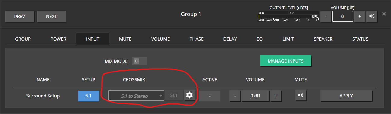
Disabling the group Input ability hides output-setup and crossmix controls.
Crossmix (upmix / downmix)
What it is
When the INPUT SOURCE layout and the group speaker layout differ, Maxx Remote needs a matrix that maps input legs to output roles. Downmix and upmix are both handled as CROSSMIX strategies.
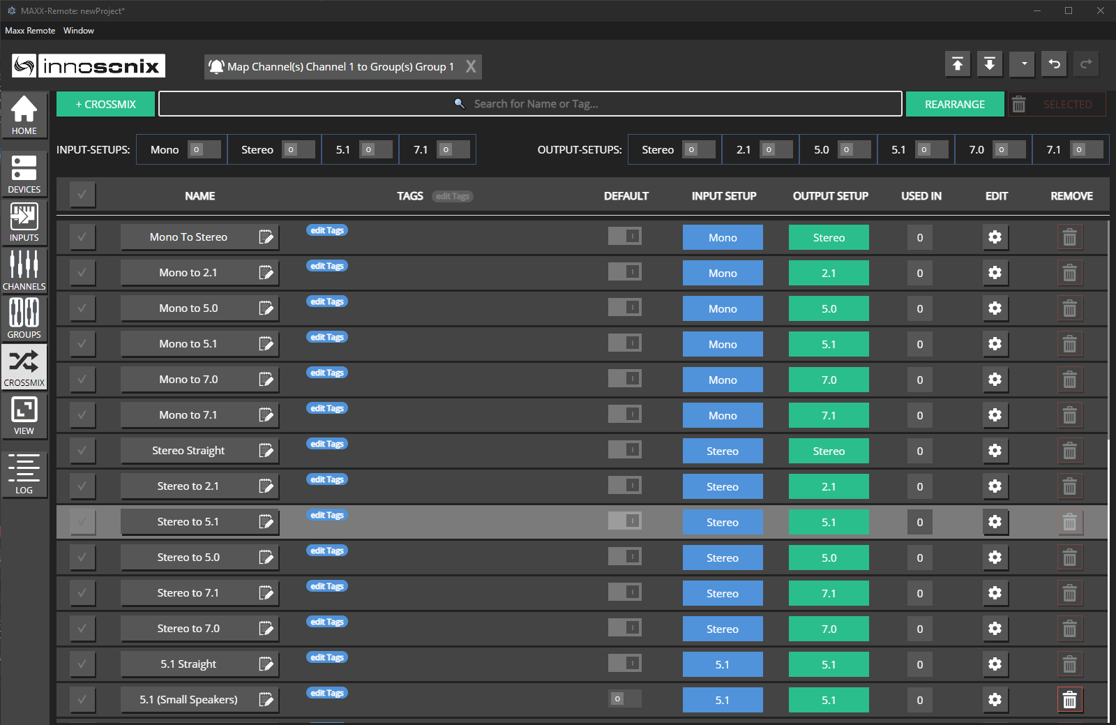
Crossmix page
Open CROSSMIX.
Review built-in strategies for each in/out pair; edit or add your own (+ CROSSMIX).
Filter by input / output setup when the list is long.
Note
Pre-defined strategies are editable (and deletable) — but a combination must always keep one global default.
Assignment priority (highest wins)
INPUT SOURCE + GROUP specific strategy
GROUP strategy for an input setup
Global default for that in/out pair
Maxx Remote always picks a strategy (even for exact matches) by checking from highest priority to lowest. Gear icons open the editor for the selected / effective strategy.
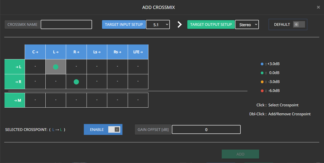
Add / edit a crossmix
Rows = output roles, columns = input legs.
Enable crosspoints (double-click, or select + Enable).
Set Gain Offset on active points (common 0 / ±3 / −6 values are color-coded).
Name the strategy to unlock Add; use Save or Save As New when editing.
Mark Default only when this should become the global fallback for that in/out pair.
You cannot change in/out setup on the current global default (would remove the fallback). Non-defaults can change freely.
Changing setup on a strategy that was assigned to a group/input clears that assignment; Maxx Remote falls back to the next strategy in the chain.
Note
Crossmix is why each input-capable group needs an output setup. Without it, Maxx Remote cannot decide whether a Left channel should get only L or a surround-to-stereo downmix.
Expected result
Surround legs land on the intended speakers; intentional up/downmix uses the strategy you selected; Dante shows the resulting subscriptions.
Common mistakes
Common mistakes
5.1 source into a stereo group with no reviewed downmix.
Forgetting LFE / Center roles in the room.
Trying to delete the only global default crossmix for a pair.
Disabling group Input ability and wondering where setup controls went.
Create, protect, and apply speaker presets for single- and multi-way channels.
Goal / when to use
Package a finished speaker tuning so you can reuse it on other channels or jobs. From Maxx Remote 1.13.0, presets are created and edited in Maxx Remote (not only on the amplifier).
Fix Out of Sync, discovery, Dante routing, and device replacement issues.
Goal / when to use
Something does not connect, discover, sync, or route audio. Work through the matching section below.
Out of Sync
Symptoms
Floating OUT OF SYNC alert in the UI
Device SYNC indicator not clean
Levels or EQ on the amp do not match Maxx Remote
Why it happens
Maxx Remote owns linked channels (Remote → device). Edits in Maxx Control, front-panel/other tools, or failed partial writes create differences. Maxx Remote detects them on periodic check-in.
Steps
Click OUT OF SYNC (or device SYNC).
Review which parameters differ.
Choose direction carefully — normal recovery is APP → DEVICE (project wins).
Use SYNC DEVICE / SYNC EVERYTHING as offered.
Optional: enable HOME AUTO SYNC so future mismatches are pushed from the project automatically.
Expected result
Sync UI clears; amp matches the project.
Important
Do not “fix” sync by randomly editing both Maxx Control and Maxx Remote. Pick Maxx Remote as source of truth for linked systems.
Device not discovered
Symptoms
ADD FROM NETWORK is empty; UI may warn that discovery on UDP 9453 is unavailable.
Steps
Confirm the amp appears in IDFM (discover) on the same PC/network.
Check PC and amp are on a discovery-friendly segment (broadcast does not cross routers).
Docker: use --network host — publishing UDP 9453 with -p is not enough for broadcast discovery. See Installation.
Select the correct NETWORK INTERFACES / RECEIVE DISCOVERY options if shown.
Fall back to ADD MANUALLY with hostname + IP.
Expected result
Device listed, or manually added and CONNECT goes online.
Dante TX sources missing in Maxx Remote
Symptoms
INPUTS / Dante discovery shows no (or stale) transmit channels, while Dante Controller on another PC may still see them.
Steps
Confirm Maxx Remote can join the Dante control network (same L2 segment as the devices).
Docker: use --network host. Dante discovery needs mDNS (224.0.0.251:5353) plus multicast 224.0.0.231:8702 and 224.0.0.233:8708 — bridge -p mappings do not deliver that reliably.
Integrator entry points for Maxx Remote — REST, operator VIEW, and signal-path URLs.
Maxx Remote exposes a few user-facing integration surfaces. This section stays thin on purpose: the live OpenAPI document on a running system is the contract for REST calls.
That document is authoritative for paths, payloads, and versions.
Scope
Compared with Maxx Control’s device REST API, this API targets the Maxx Remote project/server — operator-oriented control of the system Maxx Remote manages, not low-level single-device setup.
Maxx Remote View API: open a saved VIEW as a standalone operator web page at http://:8000/view/ (tablet / kiosk).
The Maxx Remote View API exposes a saved VIEW as a standalone operator page — without the Maxx Remote editor chrome. Operator URLs use the /view/ path (also called the View API).
What is the Maxx Remote View API?
Use it when you want tablets or dedicated operator PCs to show only the mute / volume / meter widgets you placed in VIEW, not the full project editor.
How do I open a VIEW operator page at /view/?
In VIEW, create and SAVE a page.
Copy the operator Link from the editor toolbox.
Open URLs of the form:
http://<server>:8000/view/<view-name>
(Exact name encoding matches what the UI copies.)
Expected result
Fullscreen operator canvas with the mute / volume / meter widgets you placed.