Hardware
Innosonix hardware hubs: micro MAXX compact amplifiers and accessories such as Remote Mute Server. Control and firmware docs stay under Software.
Use this section for hardware product hubs and commissioning accessories. Day-to-day control and firmware still live under Software.
| Page | Use when |
|---|
| micro MAXX series | Compact µMA PoE++ and mains amplifiers — models, power, PoE/rack notes, datasheets |
| Remote Mute Server | UDP-based remote mute (GPI-style) for MAXX amplifiers |
1 - micro MAXX series
micro MAXX compact amplifiers (µMA01/POE, µMA04/POE, µMA04/M): PoE++ or mains, onboard DSP and Dante/AES67, with the same Maxx Control API and Maxx Remote support.
micro MAXX (MICRO MAXX series) is Innosonix’s compact DSP amplifier family: GaN power stages, onboard loudspeaker management, and flexible Audio over IP (Dante / AES67). Models share the same small chassis and the same control stack as other MAXX amplifiers.
Same software as other MAXX amps
micro MAXX devices expose the same Maxx Control webpage and device REST API, and have full Maxx Remote support. Commission network and firmware with IDFM first: same path as larger MAXX chassis.
Software path
| Step | Tool | Use |
|---|
| 1 | IDFM | Discover the amp, set IP / hostname, update firmware |
| 2 | Maxx Control | Per-device browser UI and REST API (http://<ip>/) |
| 3 | Maxx Remote | Multi-amp projects, groups, offline planning |
This docs site covers Maxx Control mainly as a REST / integrator reference. Full on-device UI and DSP operator manuals are on the downloads page and product pages; not duplicated here.
Models at a glance
| Model | Power | Channels | Rated output (EIAJ, 1 kHz, 1% THD) | Notes |
|---|
| µMA01/POE | PoE / PoE+ / PoE++ | 1 | 200 W @ 4 Ω; 400 W @ 8 Ω; 400 W Hi-Z | Also supports 70 V / 100 V / 16 Ω / 8 Ω operation; full rated power with PoE++ (see below) |
| µMA04/POE | PoE / PoE+ / PoE++ | 4 | 120 W/ch @ 4 Ω and 8 Ω; bridged 240 W @ 8 Ω (2 ch) | Full rated power with PoE++ / IEEE 802.3bt; PoE / PoE+ still operate at reduced rated power (see below) |
| µMA04/M | Mains (IEC C6, 90–264 VAC) | 4 | 120 W/ch @ 4 Ω and 8 Ω; bridged 240 W @ 8 Ω (2 ch) | Optional rack-mount kit for 1–3 units in 1U |
Shared form factor: W 195.25 mm × H 39.00 mm × D 214 mm. Typical weight ≈ 1.25 kg (PoE models) / 1.35 kg (µMA04/M).
All three expose a RESTful API used with Maxx Remote, plus third-party plugins such as Q-SYS and Loxone (same integration story as other Innosonix amps; see Maxx Control third-party plugins).
PoE classes (µMA01/POE, µMA04/POE)
PoE micro MAXX models (µMA01/POE, µMA04/POE) operate on PoE, PoE+, and PoE++ (IEEE 802.3af / at / bt). Lower PoE classes still power the amplifier; they limit how much of the full rated power you can use. Use a PoE++ / IEEE 802.3bt switch or injector when you need the full rated power (for µMA04/POE: 120 W/ch @ 4 Ω and 240 W bridged @ 8 Ω).
µMA04/M is mains-powered (IEC) and is not a PoE model.
Where PoE classes come from
IEEE 802.3 defines power classes so a PSE (Power Sourcing Equipment, typically a PoE switch or injector) and a PD (Powered Device, here the micro MAXX) can negotiate a safe power budget over the Ethernet cable. The class sets two related limits:
- PSE wattage: maximum power the switch/injector may source at the port
- PD wattage: maximum power the powered device may draw at the cable end (lower than PSE because of cable loss)
Marketing names map to those IEEE types/classes roughly as follows:
| Marketing name | IEEE standard | Type | Classes | Max at PSE | Max at PD |
|---|
| PoE | 802.3af | Type 1 | 1–3 | 15.4 W | 13 W |
| PoE+ | 802.3at | Type 2 | 4 | 30 W | 25.5 W |
| PoE++ | 802.3bt | Type 3 | 5–6 | 60 W | 51 W |
| PoE++ | 802.3bt | Type 4 | 7–8 | 90 W | 71.3 W |
Per-class detail (IEEE 802.3):
| Class | Typical name | Max PSE power | Max PD power |
|---|
| 1 | PoE | 4.0 W | 3.84 W |
| 2 | PoE | 7.0 W | 6.49 W |
| 3 | PoE | 15.4 W | 13 W |
| 4 | PoE+ | 30 W | 25.5 W |
| 5 | PoE++ | 45 W | 40 W |
| 6 | PoE++ | 60 W | 51 W |
| 7 | PoE++ | 75 W | 62 W |
| 8 | PoE++ | 90 W | 71.3 W |
Class 0 is a legacy Type 1 default (treated like Class 3). Type 3/4 (802.3bt) use 4-pair power for the higher classes.
How micro MAXX uses that budget (burst power)
Rated amplifier watts on micro MAXX are audio burst figures (EIAJ-style peaks).
micro MAXX PoE models keep an internal capacitor energy store. In short:
- The PoE line recharges that store at up to the negotiated class / PD wattage.
- Loudspeaker peaks draw burst power from the capacitors, not directly as a continuous PoE draw equal to the rated audio watts.
- Between peaks, the store recharges from the PSE again.
That is why a micro MAXX can deliver high rated audio power while the Ethernet port only offers tens of watts: the cable limits the recharge rate; the capacitors supply the short burst energy for audio.
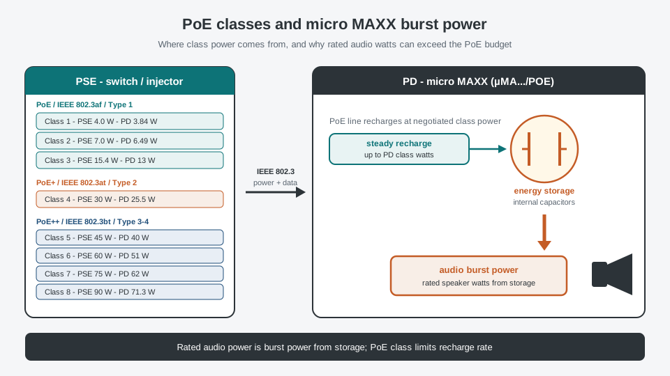
Design tip
Pick the PSE class for the sustained energy your program material needs (how often and how hard the amp must recharge), not by matching rated channel watts 1:1 to the PoE PD number. For full rated power on µMA04/POE, plan on PoE++ / 802.3bt.
Rack density (µMA04/M)
The rack-mount kit holds one, two, or three µMA04/M units in a single 1U space: up to 12 channels in 1U when three 4-channel units are fitted (each unit 120 W/ch @ 4 Ω / 8 Ω).
Datasheets & brochures
2 - Remote Mute Server (remote mute / master mute)
Remote Mute Server for MAXX: UDP remote mute, master mute, and server mute (GPI-style dead-man’s switch) across amplifiers.
Remote Mute Server provides remote mute, master mute, and server mute for MAXX amplifiers: a UDP-based GPI-style mute that emulates a classical dead-man’s switch. In all MAXX Series amplifiers, the REMOTE MUTE feature mutes the device via UDP messages when the server requests mute or stops answering.

Overview
In a typical application, a single GPI controls multiple devices, like in an acoustic research lab, where the door contact to the acoustic chamber disables the whole system to prevent hearing damage.
On the other hand, it can be used as a simple GLOBAL MUTE for the system, where the user purposely wants to activate it by hand.
All amplifiers which has the REMOTE MUTE enabled, act as an client and periodically sends requests to the configured server to ask for its current MUTE GPI state.

Note
The Device will either mute itself when:
- The server actively sends the state to be MUTE
- Or the device will not receive a response message from the server within a given time period (~400ms), so it is assumed to be ‘offline’
Protocol
For sake of simplicity and robustness, the protocol is stateless and consists of a single header with integer IDs and value. Which can also be implemented in different programming languages to use without a hardware server.
The server has to listen to UDP port 9460 for incoming REQ messages form the amplifiers.
The device will periodically send (every ~100ms) a REQ message to the server which has to be answered by the server via a RSP message, containing the MUTE STATE the device should use.
REQ MSG
Message ID “0” Client -> Server as request the MUTE state
INX_REMOTE_0
RSP MSG
Message ID “1” Server -> Client to answer the REQ message
NO MUTE:
INX_REMOTE_1_0
MUTE:
INX_REMOTE_1_1